Magnetic field coupler for fluid meter

a fluid meter and magnetic field technology, applied in the field of magnetic field couplers and fluid meter, can solve the problems of increasing cost, increasing the construction cost of many meter housings, and increasing the requirement to design, manufacture and inventory different sizes of detectors to fit the various sizes of cups, so as to eliminate all constraints on the design and size of a magnetic sensor.

Inactive Publication Date: 2005-08-16
MERCURY INSTR
View PDF2 Cites 3 Cited by
  • Summary
  • Abstract
  • Description
  • Claims
  • Application Information

AI Technical Summary

Benefits of technology

[0007]The present invention is used with fluid meters having a magnet that rotates in response to fluid flow, and the present invention provides a magnetic field coupler that eliminates all constraints on the design and size of a magnetic sensor. The magnetic field coupler of the present invention also permits a common magnetic sensor design to be used with fluid meters of many different sizes. In addition, the magnetic field coupler of the present invention permits the magnetic sensor to be better isolated from leaking fluid. The magnetic field coupler of the present invention is especially useful with rotary meters used for measuring gas flows.

Problems solved by technology

While a magnetically sensitive detector installed this way provides accurate fluid flow measurements, it does have some disadvantages.
First, the magnetically sensitive detector is often mounted on a printed circuit board assembly that contains electrical components necessary to interface with the detector.
Further, the printed circuit board assembly must be sized to fit in the cup in the meter housing; and that requirement places significant design limitations on the detector circuitry, which often leads to an increase in cost.
A second disadvantage is that different size fluid meters often have different size cups into which the magnetically sensitive detector is to be located; and the requirement to design, manufacture and inventory different sizes of detectors to fit the various sizes of cups is also costly.
A third disadvantage relates to the construction of many meter housings.
Over time, it is possible for the gasket to fail; and the fluid then leaks into the hole, thereby exposing the detector to corrosive effects, if any, of the fluid.

Method used


Image

  • Magnetic field coupler for fluid meter
  • Magnetic field coupler for fluid meter
  • Magnetic field coupler for fluid meter

Examples


Embodiment Construction

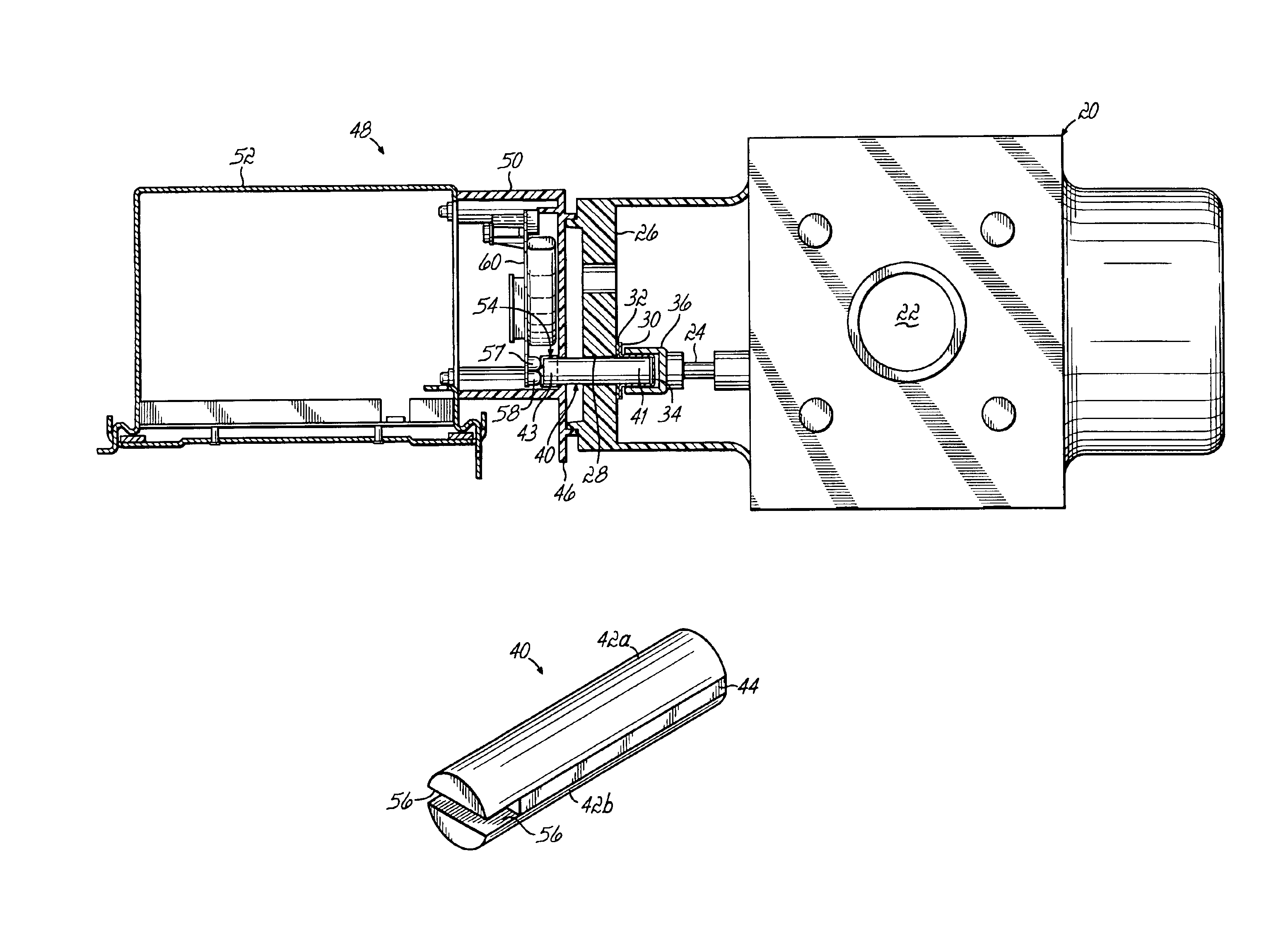
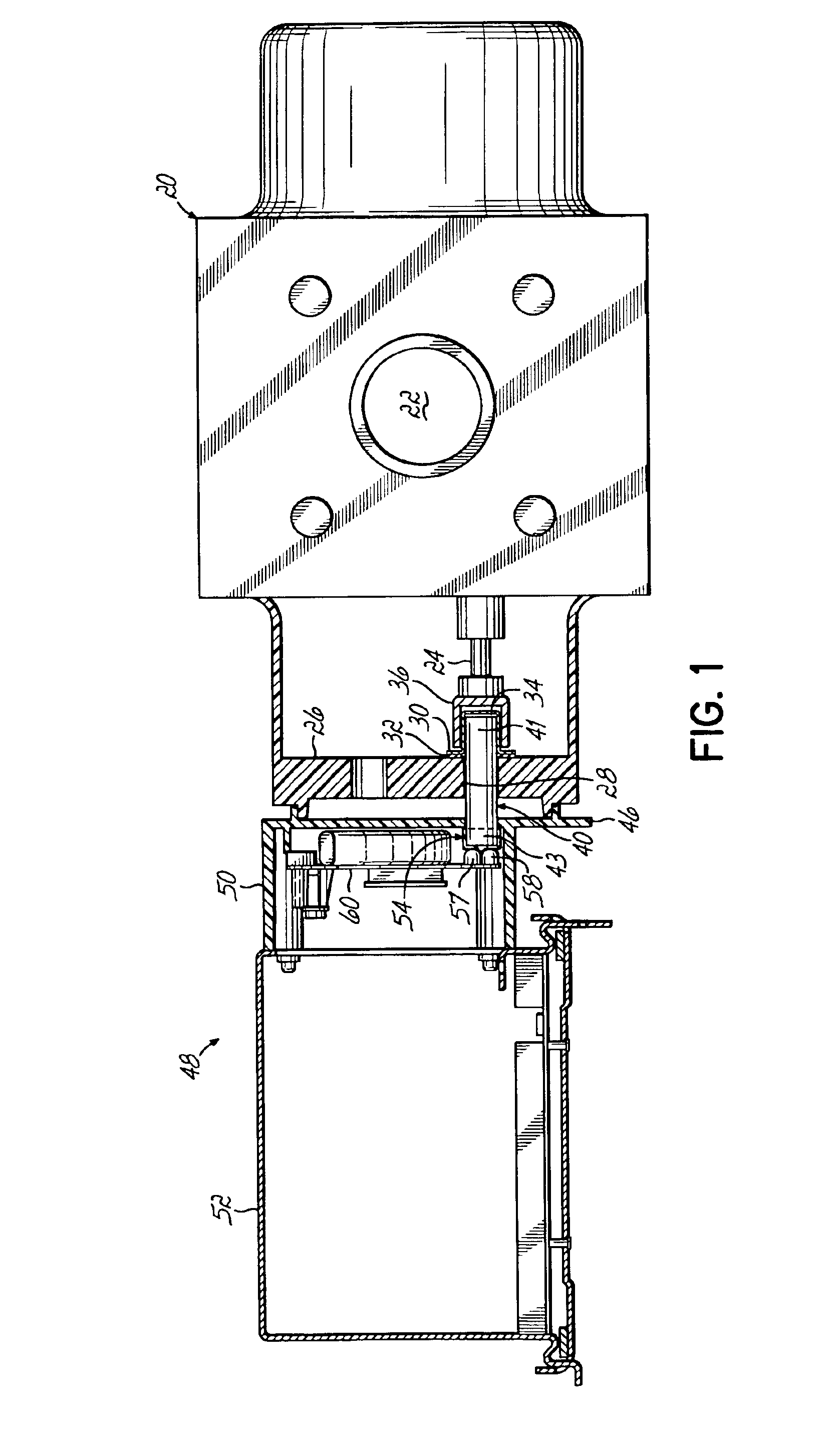
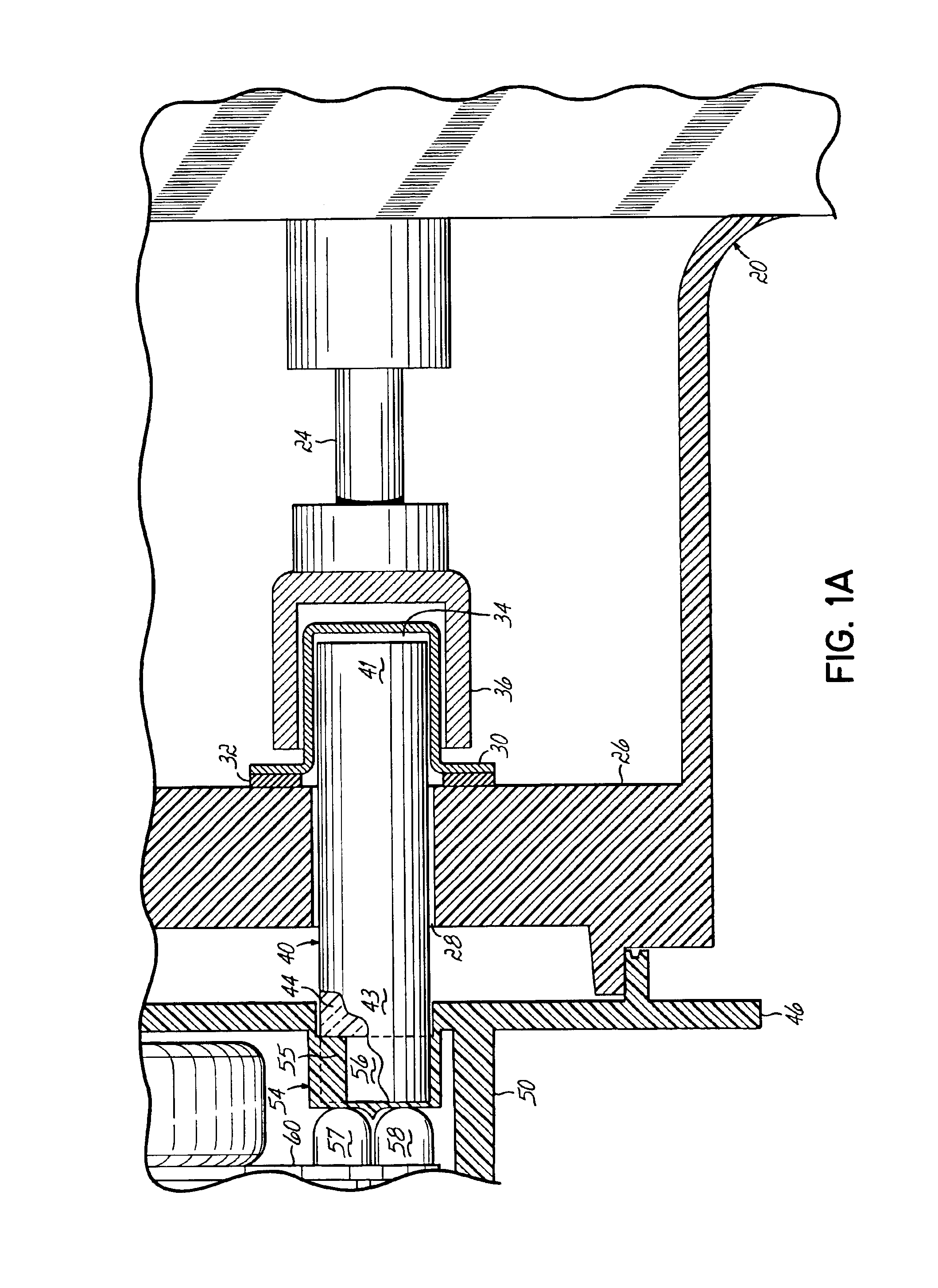
[0024]Referring to FIGS. 1 and 1A, a fluid rotary meter 20 has a fluid passage 22 for conducting a fluid therethrough. A rotary shaft 24 has blades or vanes (not shown) disposed in the fluid passage. Fluid flow through the passage 22 impacts the vanes and causes a rotation of the shaft 24 in a known manner. An wall 26 of the meter 20 has a hole 28 covered by a cup 30 that is sealed against the wall 26 by a gasket 32. The cup 30 forms a pulse well 34 extending into the meter 20. A ring-shaped magnet 36 connected to the end of the rotating shaft 24 surrounds the pulse well 34 of the cup 30.

[0025]As previously discussed, with known designs, magnetic sensors mounted on a PC board assembly are located inside the pulse well 34 to magnetically couple with the magnet 36. The present invention permits the magnetic sensor and PC board assembly to be removed from inside the meter 20 by utilizing a magnetic field coupler 40. The magnetic field coupler 40 is generally cylindrically shaped such t...


PUM


Abstract

A magnetic field coupler has a plurality of magnetic poles with respective first ends located immediately adjacent a circular path of a rotating magnet in a meter. The magnetic poles have respective opposite ends located immediately adjacent a magnetic sensor in a meter reading device. A nonmagnetic material separates each of the plurality of poles from all others of the plurality of the poles, and the nonmagnetic material is joined with the poles to form a unitary structure.

Description

[0001]This application claims the benefit of U.S. Provisional Application No. 60 / 512,363 filed on Oct. 17, 2003.FIELD OF THE INVENTION[0002]The present invention relates in general to fluid meters and more specifically, to a fluid meter having a magnet that rotates in response to fluid flow.BACKGROUND OF THE INVENTION[0003]Fluid meters, for example, those used to measure a flow of natural gas petroleum products or water, often have a shaft with one or more blades or vanes that are rotated by a flow of fluid through the meter. A magnet is often mounted on the shaft and produces a rotating magnetic field that, by mechanical, electrical, or electronic means, conveys flow information to a totalizing or rate measuring apparatus. The rotating field is often used to cause rotation of a shaft-mounted secondary magnet that, in turn, drives a mechanical totalizer or a magnetically sensitive detector generating pulses in an electrical circuit.[0004]Typically, in order to be close to the rotati...

Claims


Application Information

Patent Timeline
Patent Type & Authority Patents(United States)
IPC IPC(8): G01F1/58G01F1/56G01F1/075
CPCG01F1/075
Inventor LEHKER, WAYNE H.SNOKE, STEVEN R.VANDONKELAAR, JON L.
Owner MERCURY INSTR
Why Eureka
Try Eureka