Device for the variable control of gas exchange valves in an internal combustion engine

a technology of gas exchange valve and variable control, which is applied in the direction of valve details, valve arrangements, valve drives, etc., can solve the problem achieve the effect of small space demand, ensure valve control function, and economical valve driv

Inactive Publication Date: 2005-08-16
ROBERT BOSCH GMBH
View PDF8 Cites 5 Cited by
  • Summary
  • Abstract
  • Description
  • Claims
  • Application Information

AI Technical Summary

Benefits of technology

[0007]Depending on the pressure conditions of the pressure fluid, the piston can be extended out of or retracted into the associated cam. Thus the cam contour of the cam is continuously variable, so that arbitrary stroke curves of the gas exchange valves are attainable. In particular, the stroke height, the valve opening time, and the valve opening speed can be adjusted continuously variably. Since the retractable and extensible pistons are supported displaceably in the otherwise unmodified cams, and no changes to the tappets are required, conventional valve drives can be retrofitted with only slight modifications. Moreover, because of the integration with the cams, no additional installation space for the pistons is required, resulting in a very small demand for space. Since the camshaft is entirely preserved as a control device, the function of the valve control is assured even if the pressure fluid supply fails. Overall, with the invention, an extremely economical valve drive can be achieved, compared to the prior art.
[0009]It is also especially advantageous that the piston is kept in a defined position if the pressure fluid supply fails. As a result, the engine can continue to be operated with predetermined control times and valve strokes, without the possibility that damaging operating states will occur.
[0010]Preferably, a ball that is capable of rolling on a rolling face of a tappet that cooperates with the applicable cam is rotatably supported on the end of the piston toward the cam apex. As a result, friction losses and wear between the tappet and cam are reduced considerably. For supporting the ball, a spherical bearing face corresponding to the radius of the ball is preferably embodied on the end of the piston toward the cam apex, and its edge is crimped radially inward in order to grasp the ball. Advantageously, the bearing face of the ball is supplied with lubricant oil by the already existing lubricant oil system of the engine, so that between the bearing face, a hydrodynamic film of lubricant that is favorable in terms of both friction and wear can develop.

Problems solved by technology

Moreover, because of the integration with the cams, no additional installation space for the pistons is required, resulting in a very small demand for space.

Method used


Image

  • Device for the variable control of gas exchange valves in an internal combustion engine
  • Device for the variable control of gas exchange valves in an internal combustion engine

Examples


Embodiment Construction

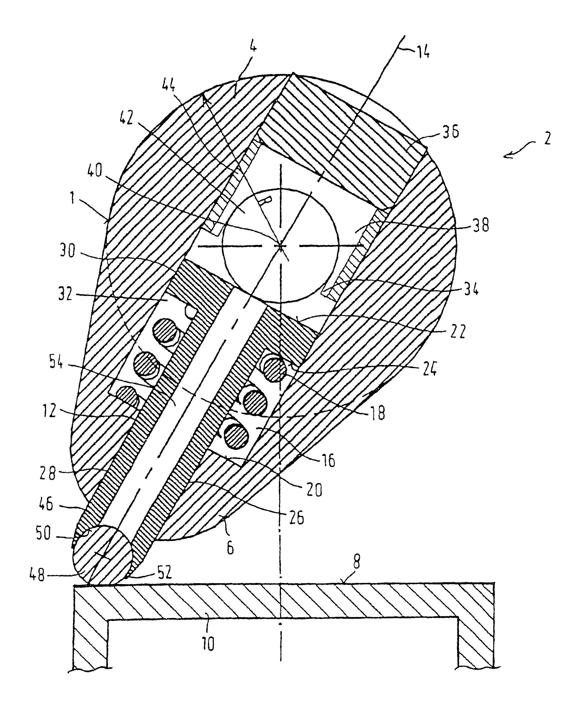
[0018]In the drawing, for reasons of scale, all that is shown of a device for variable control of the gas exchange valves of an internal combustion engine is one of a plurality of cams 1 of a camshaft 2, in cross section. The cam contour of such a cam 1 includes a circular portion 4 of the cam bottom with a cam bottom radius R and a cam apex portion 6 that is eccentric to it. In the rotary position of the cam 1 shown in the drawing, the cam apex portion 6 is in contact with a rolling face 8 of a cup tappet 10, which transmits the rotary motion of the cam 1 to the associated gas exchange valve in the form of a linear reciprocating motion.

[0019]According to the invention, for variable adjustment of the cam contour, a pressure-fluid-actuated piston 12 is provided, which is guided by the cam 1 and is radially retractable and extensible continuously and which on its end forms at least a part of the cam apex portion 6. In a preferred embodiment, the radial position of the piston 12 is adj...


PUM


Abstract

The invention relates to a device for variable control of the gas exchange valves of an internal combustion engine, of which at least one gas exchange valve is triggered by a cam of a camshaft, which cam has a cam contour with a circular portion of the cam bottom and a cam apex portion. For variably adjusting the cam contour, a pressure-fluid-actuated piston guided by the cam and retractable and extensible radially continuously, is provided which on its end forms at least a part of the cam apex portion.

Description

CROSS-REFERENCE TO RELATED APPLICATIONS[0001]This application is a 35 USC 371 application of PCT / DE 02 / 02092 filed on Jun. 8, 2002.BACKGROUND OF THE INVENTION[0002]1. Field of the Invention[0003]The invention is directed to an improved device for variable control of the gas exchange valves of an internal combustion engine, of which at least one gas exchange valve is triggered by a cam of a camshaft, which cam has a cam contour with a circular portion of the cam bottom and a cam apex portion.[0004]2. Description of the Prior Art[0005]The prior art discloses various attempts at realizing a variable control of gas exchange valves. On the one hand, partly variable valve control devices are known in which the valve strokes are variable in stages. One such valve control device is described for instance in European Patent Disclosure EP 0 515 520 B1, which has a tappet made up of two concentric cup elements, of which the inner one rests with one face end on the valve shaft of the gas exchan...

Claims


Application Information

Patent Timeline
Patent Type & Authority Patents(United States)
IPC IPC(8): F01L13/00F01L1/08
CPCF01L13/0057F01L1/08
Inventor SEBASTIAN, THOMAS
Owner ROBERT BOSCH GMBH
Why Eureka
Try Eureka