Magnetically inductive flow meter having a first electrode arrangement for galvanically inducing voltage and a second electrode arrangement for capacitively inducing voltage

a flow meter and capacitive electrode technology, applied in the direction of electromagnetic flow meters, volume/mass flow, measurement devices, etc., can solve the problems of not being suited to detecting a media state of this type, affecting the accuracy of flow meter output, etc., to achieve the effect of reducing the production cost of flow meter, reducing the amount of galvanic noise, and permanent durability and geometric stability

Inactive Publication Date: 2017-06-06
SIEMENS AG
View PDF19 Cites 1 Cited by
  • Summary
  • Abstract
  • Description
  • Claims
  • Application Information

AI Technical Summary

Benefits of technology

[0014]It is possible in an advantageous and reliable manner to determine and output a diagnostic indication regarding the state of the medium or of the flow meter by comparing a characteristic parameter of the measuring signal that is obtained using galvanically contacting electrodes to a characteristic parameter of the measuring signal that is ascertained using capacitive measuring electrodes and the diagnostic indication would not be obtainable when using only a single electrode type.
[0017]Furthermore, the invention has the advantage that after detecting an error and determining the respective cause of error it becomes possible for the user to decide whether and which maintenance measures are necessary to rectify the error.
[0018]In the case of a particularly advantageous embodiment of the invention, the first electrode arrangement that comprises galvanically contacting electrodes, and the second electrode arrangement that is achieved using capacitive electrodes are arranged in a tubular insert that is essentially formed from an electrically insulating material, where an essentially tubular metal mesh is embedded as a mechanical reinforcement in at least one measuring section, and where the metal mesh is formed from multiple galvanic mesh parts that are insulated with respect to one another. At least two of the frame parts can then be used as capacitive measuring electrodes of the second electrode arrangement, the mesh parts comprising an opening in the center for feeding through the galvanically contacting electrodes of the first electrode arrangement. This has the advantage that the capacitive electrodes are already embedded in the electrically insulating material of the tubular insert, before the insert is placed in the measuring tube. The capacitive electrodes are assembled in other words in the same working step in which the mechanical reinforcement of the tubular insert is assembled. A special assembly step for the capacitive electrodes is no longer necessary.
[0019]In an advantageous manner, a particularly simple production of the tubular insert can be achieved if the mechanical reinforcement is formed by an essentially tubular perforated sheet that is formed from stainless steel having a uniform bending radius and the mesh parts consequently form part sections of the cylinder peripheral surface of the essentially tubular metal mesh. Here, the mesh parts are embedded in their galvanic insulation in a spacing with respect to one another in the electrically insulating material. The spacing between the mesh parts is dimensioned such that the mechanical stability of the tubular insert is ensured by the electrically insulating material that bridges the spacing.
[0021]A tubular insert of this type can be pre-assembled in an advantageous manner entirely outside the measuring tube with the previously embedded metal mesh for mechanical reinforcement and in order to achieve the capacitive electrodes. In an advantageous manner, the production outlay of the flow meter is therefore kept small. Furthermore, the tubular insert characterizes itself by a permanent durability and geometric stability as a result of the mechanical reinforcement using the metal mesh.
[0022]In the case of a particularly advantageous embodiment of the invention, the controller / evaluator is configured to determine the measured value for the flow of the medium that is to be measured dependent upon both the first measuring signal that corresponds to the voltage that is determined using the galvanically contacting electrodes as well as the second measuring signal that is ascertained using capacitive electrodes. Capacitive electrodes are namely less sensitive with respect to the above described effects of a multiphase flow and place smaller demands upon the electrical conductivity of the medium that is to be measured so that overall a higher degree of accuracy and versatility of the flow meter is achieved.

Problems solved by technology

Electrode materials that are in direct contact with an electrically conductive medium, for example, always cause a certain amount of galvanic noise.
However, for the same reason, the capacitive electrodes are, on the other hand, not as well suited to detecting a media state of this type, in other words a multiphase flow.

Method used


Image

  • Magnetically inductive flow meter having a first electrode arrangement for galvanically inducing voltage and a second electrode arrangement for capacitively inducing voltage
  • Magnetically inductive flow meter having a first electrode arrangement for galvanically inducing voltage and a second electrode arrangement for capacitively inducing voltage

Examples


Embodiment Construction

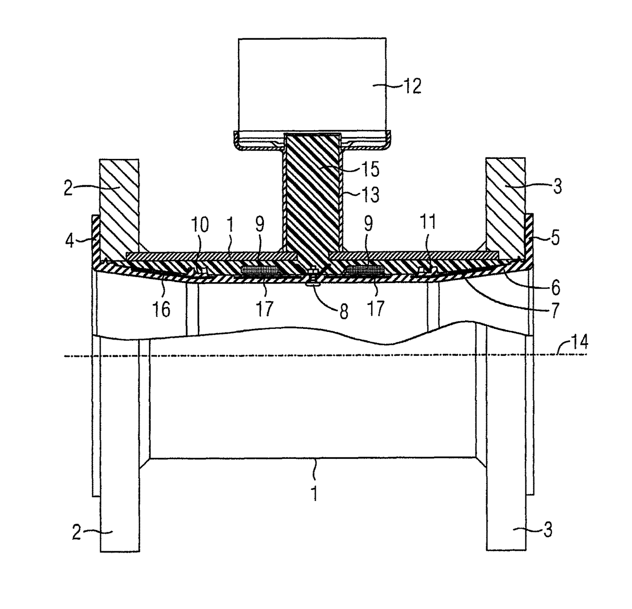
[0027]A magnetically inductive flow meter comprises in accordance with FIG. 1 a measuring tube 1 that is provided with a flange 2 or a flange 3, respectively, on its two ends for installing in a pipe line. In the upper part of FIG. 1, the flow meter is illustrated in a longitudinal section for improved clarity. Each of the outer sides of the two fastening flanges 2 and 3 comprise an end section 4 or 5, respectively, that is formed in a flange-like manner of a tubular insert 6 that is made from rubber. To a large extent, the tubular insert 6 is rotationally symmetrical with respect to an axis 14 and supports two coils as magnetic field generating devices in a known manner in a measuring section in which the insert is mechanically reinforced by an essentially tubular metal mesh 7, 16, 17. Only one of the coils 9 is visible in FIG. 1. With a first electrode arrangement that comprises two electrodes that galvanically contact the medium, the electrodes lying opposite one another in relat...


PUM


Abstract

A magnetically inductive flow meter including a first electrode arrangement for galvanically contact detection of an induced voltage dependent on the flow velocity of the medium as a first measurement signal, and a second electrode arrangement for capacitive detection of an induced voltage as a second measurement signal, wherein by determining and evaluating characteristic parameters of the first and second measurement signals, diagnostic messages on the status of the medium and / or the flow meter are obtained, such as the content of gas bubbles in the fluid, electrode corrosion, electrical conductivity of the medium, damage to the electrically insulating interior lining of the measuring tube, deposits on electrodes, magnetic interference fields, electrode short-circuits and / or the fill level of the measuring tube.

Description

CROSS-REFERENCE TO RELATED APPLICATIONS[0001]This is a U.S. national stage of application No. PCT / EP2013 / 074238 filed 20 Nov. 2013. Priority is claimed on German Application No. 10 2012 221 616.2 filed 27 Nov. 2012, the content of which is incorporated herein by reference in its entirety.BACKGROUND OF THE INVENTION[0002]1. Field of the Invention[0003]The invention relates to a magnetically inductive flow meter having a measuring section surrounded by a wall, where a medium flows through the measuring section, and the magnetically inductive flow meter also has a magnetic field generating device, an electrode arrangement and a controller / evaluator.[0004]2. Description of the Related Art[0005]Magnetically inductive flow meters use Faraday's induction principle to determine the flow rate of a fluid that is flowing through the flow meter. A magnetic field is generated perpendicular to the flow direction. A voltage perpendicularly to the magnetic field and to the flow direction occurs in ...

Claims


Application Information

Patent Timeline
Patent Type & Authority Patents(United States)
IPC IPC(8): G01F1/58
CPCG01F1/584
Inventor ISIK-UPPENKAMP, SONNUR
Owner SIEMENS AG
Why Eureka
Try Eureka