Method and arrangement for feeding wood batches into a pressure grinder

a pressure grinder and wood batch technology, applied in the field of pressure grinder feeding a wood batch, can solve the problems of increasing costs, affecting the operation of the groundwood mill,

Inactive Publication Date: 2005-08-16
VALMET TECH INC
View PDF5 Cites 5 Cited by
  • Summary
  • Abstract
  • Description
  • Claims
  • Application Information

AI Technical Summary

Benefits of technology

[0006]It is an object of the present invention to provide a method and an arrangement for feeding wood batches from a wood f...

Problems solved by technology

However, as to transferring and feeding the wood batches in particular, this solution has certain limitations, since wood must be transported and fed into the feeding chamber from the side to avoid the problems caused by the dropping.
In c...

Method used


Image

  • Method and arrangement for feeding wood batches into a pressure grinder
  • Method and arrangement for feeding wood batches into a pressure grinder
  • Method and arrangement for feeding wood batches into a pressure grinder

Examples


second embodiment

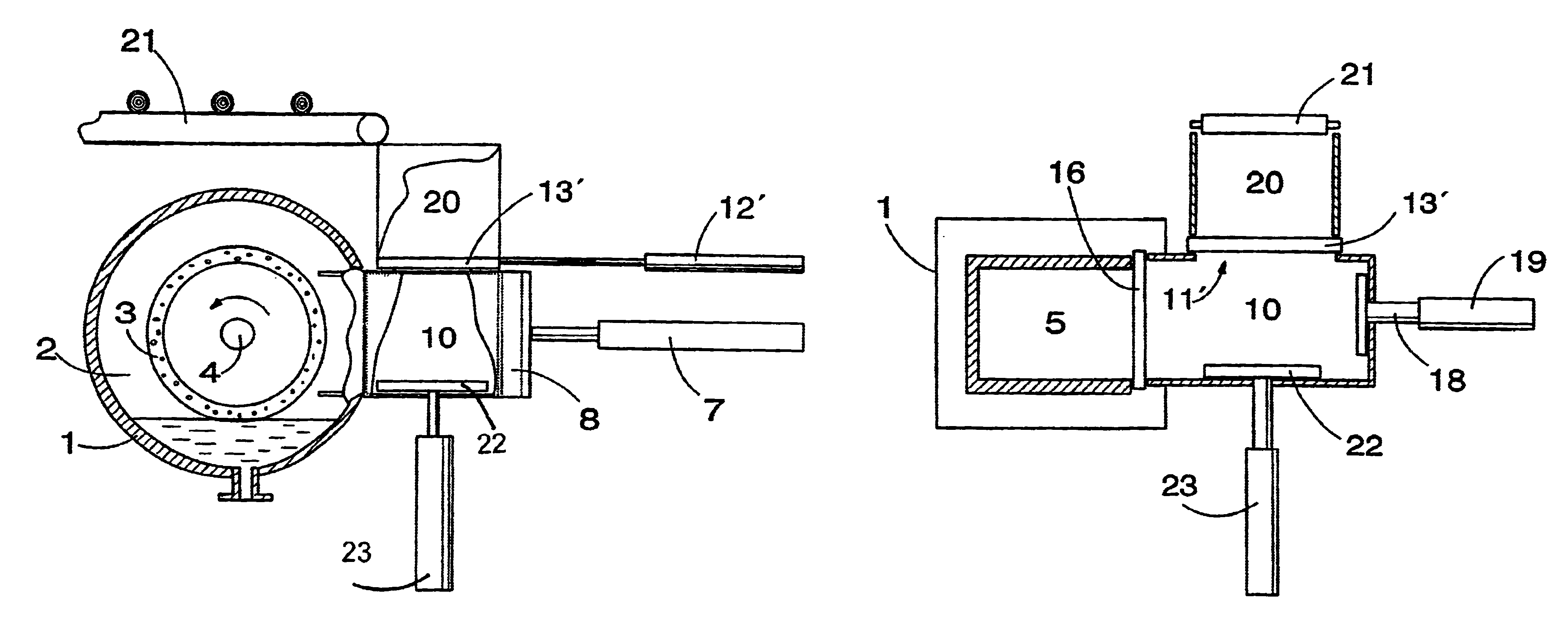
[0025]FIGS. 4a to 4c, in turn, show the method and arrangement of the invention. In this embodiment, as FIG. 4a shows, a wood batch is dropped onto the closing sluice 13′ of the batch chamber 20 to wait until it is possible to lower the batch to the side feeding chamber 10. The wood in the side feeding chamber 10 was already transferred into the feeding chamber 5 earlier in a manner shown in FIGS. 3a to 3c and the transfer piston 18 is brought back to the end of the side feeding chamber 10. The supporting plate 22, for its part, is lifted up in a manner shown in the figure so that it is immediately under the closing sluice 13′ ready to receive a wood batch from the batch chamber 20.

[0026]FIG. 4b shows a situation where the closing sluice 13′ is pulled to the side from under the wood batch and the wood batch is lowered onto the supporting plate 22 so that the walls of the batch chamber 20 keep it in good order.

[0027]FIG. 4c, in turn, shows a situation where a wood batch is lowered wi...

third embodiment

[0028]FIG. 5 schematically shows the method and arrangement of invention, which otherwise corresponds to the embodiment of FIGS. 3a to 3c, but the operational distance of the supporting plate 22 is longer than in the other embodiments. In this embodiment, the supporting plate 22 can be lifted nearly as high as to the level of the conveyor 21. In this case, logs of wood supplied from the conveyor 21 to the supporting plate 22 fall only a short distance, and therefore they do not move restlessly nor are they set obliquely onto the supporting plate 22. When new logs are fed onto the supporting plate 22 in the batch chamber 20, the supporting plate 22 is simultaneously lowered so that the falling distance of new logs remains quite short, until a suitable batch of wood is formed on top of the supporting plate 22 and it can be lowered through the opening 11′ to the side feeding chamber 10.

fourth embodiment

[0029]FIGS. 6a to 6c show the method and arrangement of the invention, which may be a solution based on one of the embodiments of the invention shown above, whereby the numbering of the parts corresponds to the numbering previously used for identical parts. This embodiment of the invention differs from the previous embodiments in that it comprises a separate transfer support 24, which is used for maintaining a wood batch in a suitable shape during the transfer. The transfer support 24 is a trough provided with an opening on its upper side or a supporting frame formed by sides connected to each other in the transverse direction, into which transfer support a wood batch is lowered by means of the supporting plate 22 so that it is supported by the side walls 24a of the transfer support 24. When the wood batch is transferred from the side feeding chamber 10 into the feeding chamber 5, the transfer support 24, along with the wood batch, is simultaneously transferred by using the transfer...


PUM

PropertyMeasurementUnit
Pressureaaaaaaaaaa
Shapeaaaaaaaaaa

Abstract

A method of feeding a wood batch into a pressure grinder, the method comprising first collecting the wood batch to be fed into the grinder into a separate batch chamber above a side feeding chamber, from which the wood batch is lowered vertically by means of a separate supporting plate to the side feeding chamber. Thereafter, the wood batch is transferred from the side feeding chamber into the feeding chamber. An arrangement for feeding a wood batch into a pressure grinder comprises a batch chamber above a side feeding chamber and in which the wood batch to be fed into the pressure grinder is formed before it is lowered into the side feeding chamber.

Description

BACKGROUND OF THE INVENTION[0001]1. Field of the Invention[0002]The invention relates to a method for feeding a wood batch into a pressure grinder, according to which method the wood batch is transferred first into a side feeding chamber, which is pressurizable to the same pressure as a continuously pressurized grinding chamber, and thereafter from the side feeding chamber into a feeding chamber where the wood batch is during grinding pushed into contact with a grinding element, such as a pulp stone, rotating in the grinding chamber, whereby the wood batch is transferred substantially horizontally from the side feeding chamber into the feeding chamber in the direction of the rotation axis of the grinding element.[0003]The invention also relates to an arrangement for feeding wood batches into a pressure grinder, the arrangement comprising a frame forming a pressurizable grinding chamber, a rotating grinding element in the grinding chamber, a feeding chamber opening to the grinding ch...

Claims


Application Information

Patent Timeline
IPC IPC(8): D21B1/00D21B1/24
CPCD21B1/24Y10S241/14
Inventor HAIKKALA, PEKKAHARAKKAMAKI, KARISETALA, SIMO
Owner VALMET TECH INC
Why Eureka
Try Eureka