
Engine variable valve timing system

a timing system and variable valve technology, applied in the direction of valve arrangement, oscillating piston engine, machines/engines, etc., can solve the problems of delayed response in advance/retard control engine speed becoming unstable, etc., and achieves the effect of easy bled and easy bled

Inactive Publication Date: 2005-03-01
MAZDA MOTOR CORP
View PDF10 Cites 4 Cited by
  • Summary
  • Abstract
  • Description
  • Claims
  • Application Information

AI Technical Summary

Benefits of technology

The present invention provides an engine variable valve timing system that can reduce the overlap of valves when the engine is idling or at the time of engine start-up. This system includes a hydraulic variable intake phase mechanism and a hydraulic variable exhaust phase mechanism, which have advancing and retarding hydraulic pressure chambers and control valves to control the timing of valves. The system also includes annular grooves on the camshaft bearing surfaces, which improve the responsiveness of the hydraulic pressure and achieve quick retarding and advancing control on the valves. The position of the annular grooves helps to reduce the loss of retarding hydraulic pressure on the intake side and the occurrence of stalls. The system also ensures reliable and easy return of the exhaust camshaft to the advancing direction even when the engine is halted or started.

Problems solved by technology

However, if the overlap period during which the intake and exhaust valves are both open is large such as during idling, for example, deleterious effects such as the engine speed becoming unstable may occur, so in this case, it is customary to attempt to shorten the overlap (i.e, advance the open / close timing of the exhaust valve and / or retarding the open / close timing of the intake valve) and thus suppress the suckback of exhaust from the exhaust line.
However, there is the problem of the response lag of hydraulic fluid from when the signals for advance / retard control are output until the advancing hydraulic pressure and the retarding hydraulic pressure are supplied to or discharged from the advancing hydraulic pressure chamber or the retarding hydraulic pressure chamber, and the valve timing is actually advanced or retarded.
If this happens, the engine speed becomes unstable as described above, possibly leading to a stall.
More specifically, delay in the supply of retarding hydraulic pressure to the retarding hydraulic pressure chamber of the variable intake phase mechanism or delay in the supply of advancing hydraulic pressure to the advancing hydraulic pressure chamber of the variable exhaust phase mechanism may result in delayed response in advance / retard control, so when changing the overlap from large to small, it will not become small immediately.
In addition, when the previous engine halt occurred suddenly, as when going from a high-load state without adequately passing through the idling state, or in the case of a stall or the like, because of the hydraulic fluid response lag described previously, it is possible that the intake and exhaust camshafts may not have returned adequately to the side of narrow overlap (the exhaust camshaft on the advanced side, the intake camshaft on the retarded side).
Even in this case, it is sufficient for the hydraulic pressure to rise at the time of the next engine start and for the camshafts to return promptly to the side of narrowing the overlap, but when the engine halts the hydraulic pumps are also halted and supply no hydraulic pressure, so while the engine is halted the hydraulic fluid is bled from the hydraulic pressure chambers and the hydraulic lines connecting these hydraulic pressure chambers to the hydraulic pressure control valves described above, so one cannot expect the hydraulic pressure to rise immediately upon the next engine start.
As a result, the engine is started in the state in which the open / close timing of the intake / exhaust valves is not appropriate (the overlap is not sufficiently narrow), so there is a problem in that the engine ignition and starting performance become poor.
Thus, while the intake camshaft is naturally or easily returned in the retarding direction that narrows the overlap while the engine is halted or at the time of an engine start, the exhaust camshaft is not easily returned in the advancing direction that narrows the overlap.
There are further problems that may occur in variable phase mechanisms on which a lock mechanism is mounted.
However, the hydraulic pumps are also halted when the engine is halted, so the hydraulic fluid that had flowed in the hydraulic lines drains downward and air enters these hydraulic lines.
Moreover, at this time, the air within this hydraulic line is first pushed out by the hydraulic pressure supplied to the advancing hydraulic line, and there is a possibility that this air may knock the lock pin of this lock mechanism out from the indentation.
Furthermore, at that point in time, the exhaust-side advancing hydraulic pressure (hydraulic line) and the intake-side retarding hydraulic pressure have not yet reached the advancing hydraulic pressure chamber and the retarding hydraulic pressure chamber, so ultimately problems occur wherein the rotor and camshaft positions fluctuate unstably, abnormal sounds are caused by shimmying in the direction of rotation between the rotor formed as a unit with the camshaft and the casing formed as a unit with the sprockets which form the hydraulic pressure chambers, or the position of the rotor and camshaft shifts from the advanced-side position, making the rotation during idling become unstable.

Method used


Image

  • Engine variable valve timing system
  • Engine variable valve timing system
  • Engine variable valve timing system

Examples


Embodiment Construction

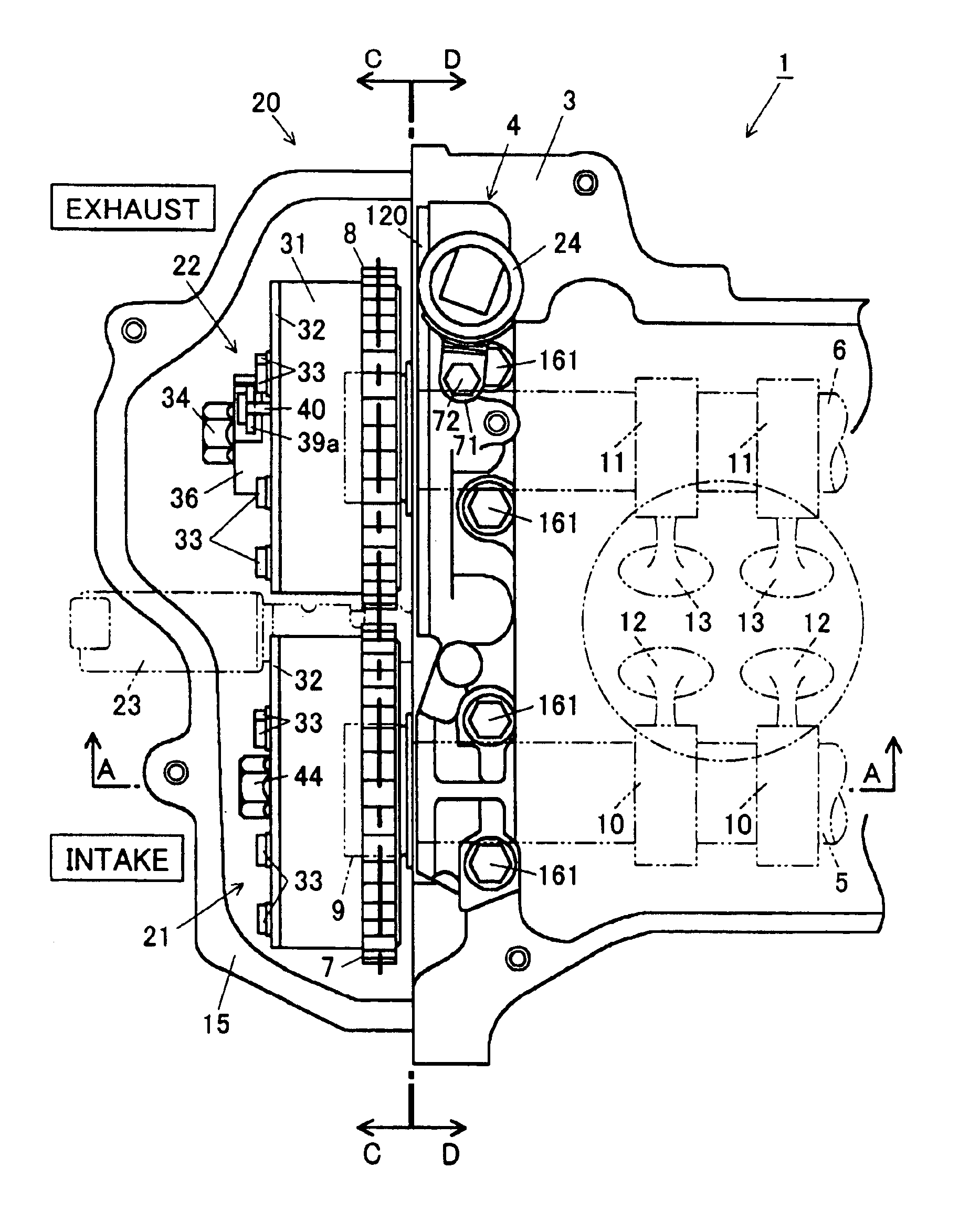
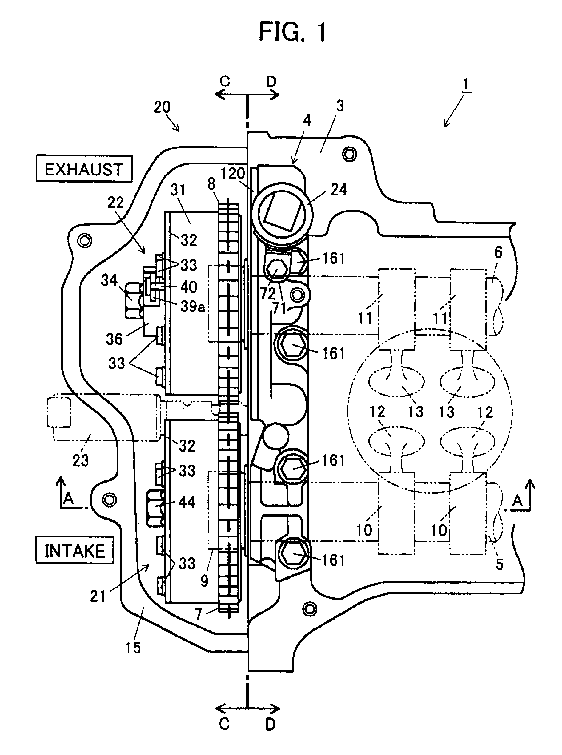
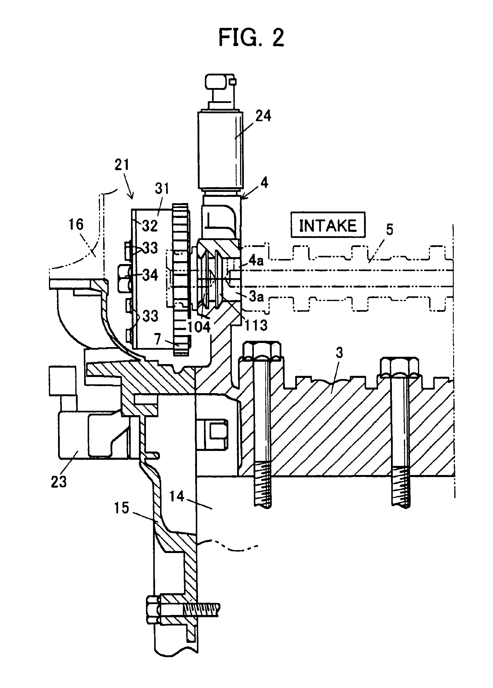
Preferred embodiments of the present invention will now be explained. As shown in FIGS. 1 and 2, an engine 1 is provided with an intake camshaft 5 and an exhaust camshaft 6 which are disposed parallel to a crankshaft (not shown but given the reference numeral 2) and rotatably supported by a cylinder head 3 and a cam cap 4. In the vicinity of the ends of these camshafts 5 and 6, sprockets 7 and 8 which are capable of relative rotation within a stipulated range are engaged to these camshafts 5 and 6 and also a chain 9 is wound around these sprockets 7 and 8 and a sprocket on the crankshaft 2 side. Moreover, with the rotation of the chain 9, the sprockets 7 and 8 and the camshafts 5 and 6 rotate via the chain 9, and thereby, via a plurality of cams 10 and 11 (see FIG. 1) secured to each of the camshafts 5 and 6, a plurality of intake valves 12 and exhaust valves 13 are driven to open and close.

Here, as shown in FIG. 2, mounted to the cylinder block 14 and end surface of the cam cap 4 o...


PUM


Abstract

In the variable valve timing system according to the present invention, portions of the intake-side advancing hydraulic line and a retarding hydraulic line respectively constitute annular grooves 104 and 113 for advancing and retarding provided on the intake camshaft 5 bearing surface 5a of the cam cap 4 which supports the camshafts 5 and 6. In addition, portions of the advancing hydraulic line and the retarding hydraulic line for exhaust respectively constitute annular grooves for advancing and retarding 123 and 133 provided on the exhaust camshaft 6 bearing surface 4b of the cam cap 4. Moreover, the annular groove for retarding 113 on the intake camshaft 5 bearing surface 4a and the annular groove for advancing 123 on the exhaust camshaft 6 bearing surface 4b are respectively provided in the center in the width direction of their respective bearing surfaces 4a and 4b.

Description

BACKGROUND OF THE INVENTION1. Field of the InventionThe present invention relates to an engine variable valve timing system and particularly to an engine variable valve timing system equipped with a hydraulic variable intake phase mechanism and a hydraulic variable exhaust phase mechanism.2. Description of the Related ArtRecent automotive engines are equipped with variable valve timing systems that vary the timing at which the intake and exhaust valves open and close. These variable valve timing systems typically have variable phase mechanisms that vary the phases of the camshafts with respect to the crankshaft. Such variable phase mechanisms have conventionally been disposed on the ends of the intake camshaft and the exhaust camshaft. Variable phase mechanisms comprise a sprocket linked by chain to the crankshaft, a housing formed as a unit with the sprocket and a rotor formed as a unit with a camshaft enclosed within the housing, so that an advancing hydraulic pressure chamber and...

Claims


Application Information

Patent Timeline
Patent Type & Authority Patents(United States)
IPC IPC(8): F01L1/344
CPCF01L1/022F01L1/3442F01L2001/0537F01L2001/34426Y10T74/2102F01L2001/34433F01L2001/34469F01L2001/34483F01L2001/3443
Inventor ASAI, AKIRAFUKUMA, MASAKINAITO, MASAHIROSHIMIZU, KOUICHITAKAHASHI, IKUMATOMIZAWA, KAZUHIRO
Owner MAZDA MOTOR CORP
Learn More