Method and device for operating an internal combustion engine

a technology of internal combustion engine and combustion chamber, which is applied in the direction of machines/engines, output power, mechanical apparatus, etc., can solve the problems of limited maximum catalytic converter exotherm, etc., and achieve the effects of improving mixing, increasing post-reaction rate, and increasing the rate of reaction

Inactive Publication Date: 2014-03-18
ROBERT BOSCH GMBH
View PDF10 Cites 4 Cited by
  • Summary
  • Abstract
  • Description
  • Claims
  • Application Information

AI Technical Summary

Benefits of technology

[0007]The scavenging operating mode can improve the non-stationary and stationary performance of the charge device in that the air charge into the cylinders of the internal combustion engine, i.e. the fresh air mass flow conveyed through the cylinders, is increased, so that the transient load buildup is accelerated, or the stationary end value of the engine torque is increased. The degree of scavenging, which is determined by the fresh air mass conveyed through the cylinders, is limited at the exhaust side by, among other things, a catalytic converter situated there. On the one hand, the conversion in the catalytic converter can take place only within a limited lambda range, and on the other hand the maximum catalytic converter exothermy is limited.
[0011]The above method makes it possible to improve the mixing process upstream from the turbine, so that the post-reaction takes place earlier. Through the offset operation of the exhaust valves of a cylinder, the fresh air of one of the partial exhaust ducts, conveyed into the partial exhaust ducts by the scavenging operation, is first conveyed in the direction of the turbine, and subsequently, after a part of the combustion exhaust gas that was conveyed through the first-opened exhaust valve and through the partial exhaust duct into the common exhaust duct, a further exhaust valve is opened in order to convey the fresh air column of the further partial exhaust duct into the common exhaust duct. This improves the homogenization of fresh air and exhaust gas in the common exhaust duct, and post-reactions in the exhaust tract of the internal combustion engine can take place earlier before reaching the turbine of the charge device. This enables a higher turbine power because the convertible exhaust gas enthalpy in the turbine is greater.
[0012]Through the above method, in general the use of exhaust gas enthalpy in scavenging operating mode is increased by exhaust gas post-reactions in that the mixing of rich exhaust gas, i.e. a combustion exhaust gas having an uncombusted fuel portion, with fresh air is improved and is realized closer to the engine. In this way, there result greater degrees of freedom for the scavenging operating mode, and smaller dimensions of the internal combustion engine are made possible. In this way, reductions in consumption and a reduction of CO2 emissions can be realized.
[0016]A further advantage of the phase-shifted opening of the exhaust valves results due to the strongly non-homogenous speed profile of the gases at the junction of the partial exhaust ducts. Thus, large-scale turbulences and a strong swirl flow are generated in an exhaust gas manifold pipe situated after the junction. The increased rate of post-reactions in connection with the swirl flow results in an additional homogenization in the junction of the exhaust gas manifold pipes of the individual cylinders before the turbine of the charge device.
[0017]A further advantage of the above method is an improvement of the mixing independent of installed parts or manifold geometry, so that for various engine types the exhaust gas enthalpy is increased due to the increased rate of post-reactions, so that this enthalpy can be made more useful. In this way, the scavenging operation mode can be expanded, and problems with transient load buildup can thus be solved more easily.

Problems solved by technology

On the one hand, the conversion in the catalytic converter can take place only within a limited lambda range, and on the other hand the maximum catalytic converter exothermy is limited.

Method used


Image

  • Method and device for operating an internal combustion engine
  • Method and device for operating an internal combustion engine
  • Method and device for operating an internal combustion engine

Examples


Embodiment Construction

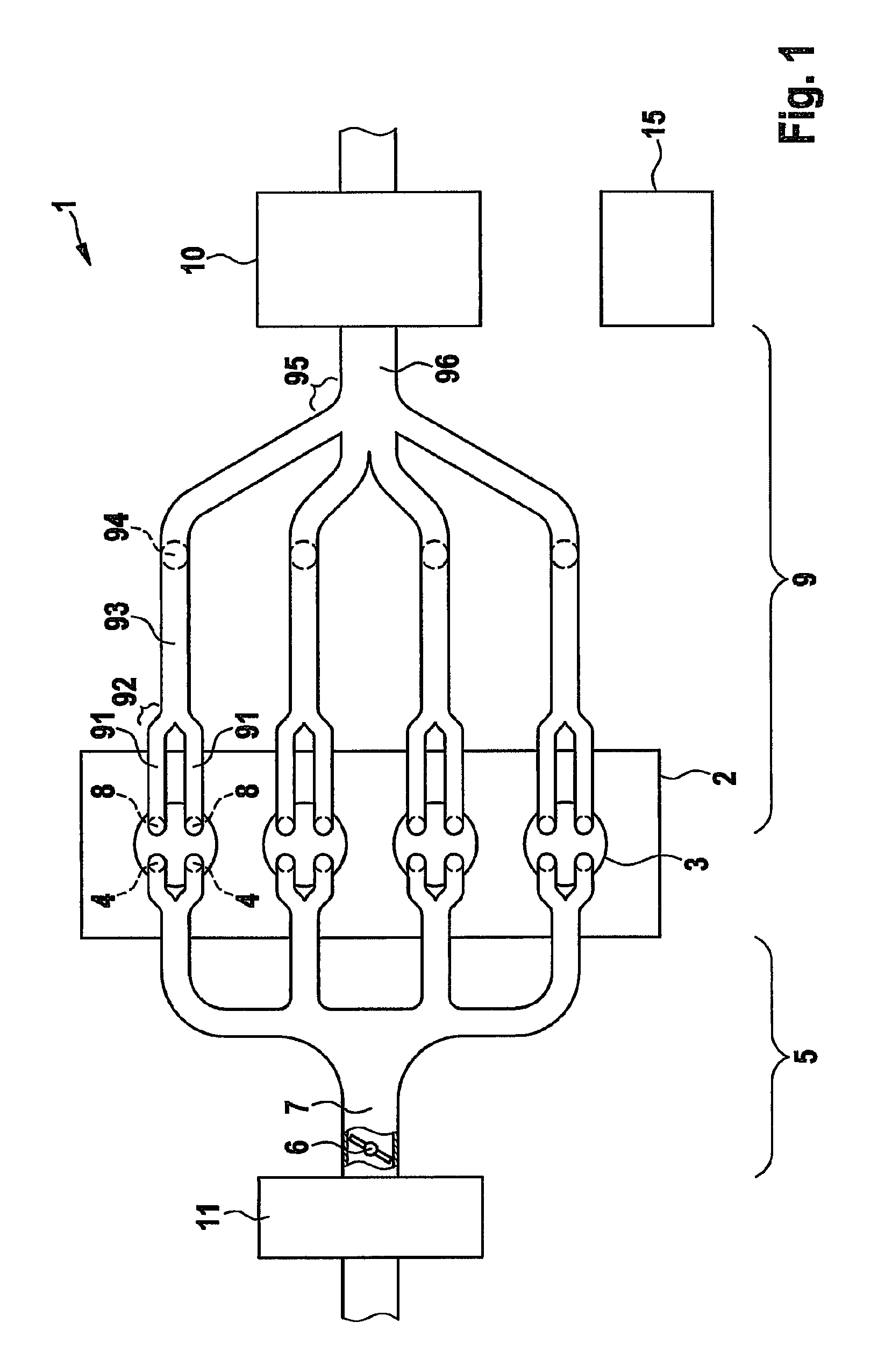
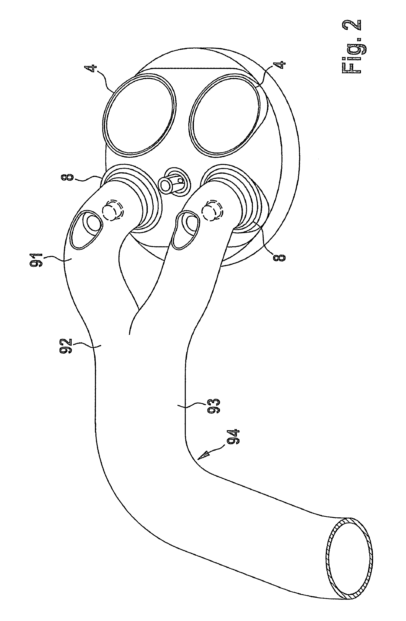
[0031]FIG. 1 shows a schematic representation of an engine system 1 having an internal combustion engine 2 which in the depicted exemplary embodiment has four cylinders 3. The internal combustion engine is for example a spark-ignition engine. Cylinders 3 each have two intake valves 4 connected to an air supply system 5. Via air supply system 5, fresh air can be supplied to intake valves 4, which, corresponding to their controlling, admit the fresh air into a combustion chamber of the corresponding cylinder 3 as a function of the respective working stroke of cylinder 3.

[0032]Fuel is preferably supplied to cylinders 3 directly, via a corresponding injection valve (not shown). The air supply is set in air supply system 5 via a throttle valve 6, the position of throttle valve 6 specifying an intake pipe pressure in intake pipe segment 7. The intake pipe pressure determines the quantity of fresh air that flows or is suctioned into the combustion chamber of cylinder 3 when the correspondi...


PUM


Abstract

In a method for operating an internal combustion engine having at least one cylinder which includes a first exhaust valve and a second exhaust valve, the internal combustion engine is operated in a scavenging operating mode in that the closing times of the exhaust valves after an ejection stroke of a four-stroke operating cycle are situated after an opening time of an intake valve, and the second exhaust valve is opened with a time delay relative to the first exhaust valve in the scavenging operating mode.

Description

BACKGROUND OF THE INVENTION[0001]1. Field of the Invention[0002]The present invention relates to internal combustion engines, in particular to internal combustion engines that can be operated in a scavenging operating mode.[0003]2. Description of the Related Art[0004]In order to improve engine efficiency in partial load operation, the displacement of internal combustion engines is continually being reduced. The loss of power connected therewith is compensated by providing charge devices that provide fresh air to the internal combustion engine under increased charge pressure. In particular when exhaust gas turbochargers are used as charging devices, deficits result during the rapid buildup of load required to ensure a good torque characteristic of the vehicle for rapid accelerations. These disadvantages can be compensated by a scavenging operating mode in which fresh air is flushed through the cylinders through a valve overlap of the opening phase of the intake valves and the opening...

Claims


Application Information

Patent Timeline
Patent Type & Authority Patents(United States)
IPC IPC(8): F02B25/00
CPCF02D13/0257F02B25/145Y02T10/18F02B37/00F02D13/0261F02D13/0219Y02T10/12F02D13/02F02B47/08
Inventor BRANDT, MARTINBETZLER, PERRY
Owner ROBERT BOSCH GMBH
Why Eureka
Try Eureka