Pneumatic lift device

Inactive Publication Date: 2005-08-16
KIM SUN Y
View PDF5 Cites 40 Cited by
  • Summary
  • Abstract
  • Description
  • Claims
  • Application Information

AI Technical Summary

Benefits of technology

[0008]The air bladder is contained between the lift platform and based by the four side panels. Inflation of the air bladder is accomplished by any conventional electric or mechanical air pump. Typically for consumer use, the contained air bladder is inflated at no more than 1 or 2 p.s.i. When spread over the area of the lift platform the pneumatic lift device can lift an object hundreds of pounds in weight. It is to be understood that the preferred designs are inexpensive, light in weight, and preferably mass produced in plastic. In this manner the cost of a pneumatic lift

Problems solved by technology

In this manner the cost of a pneumatic lift unit is exceptionally low and a household pneumatic lift device may

Method used


Image

  • Pneumatic lift device
  • Pneumatic lift device
  • Pneumatic lift device

Examples


Embodiment Construction

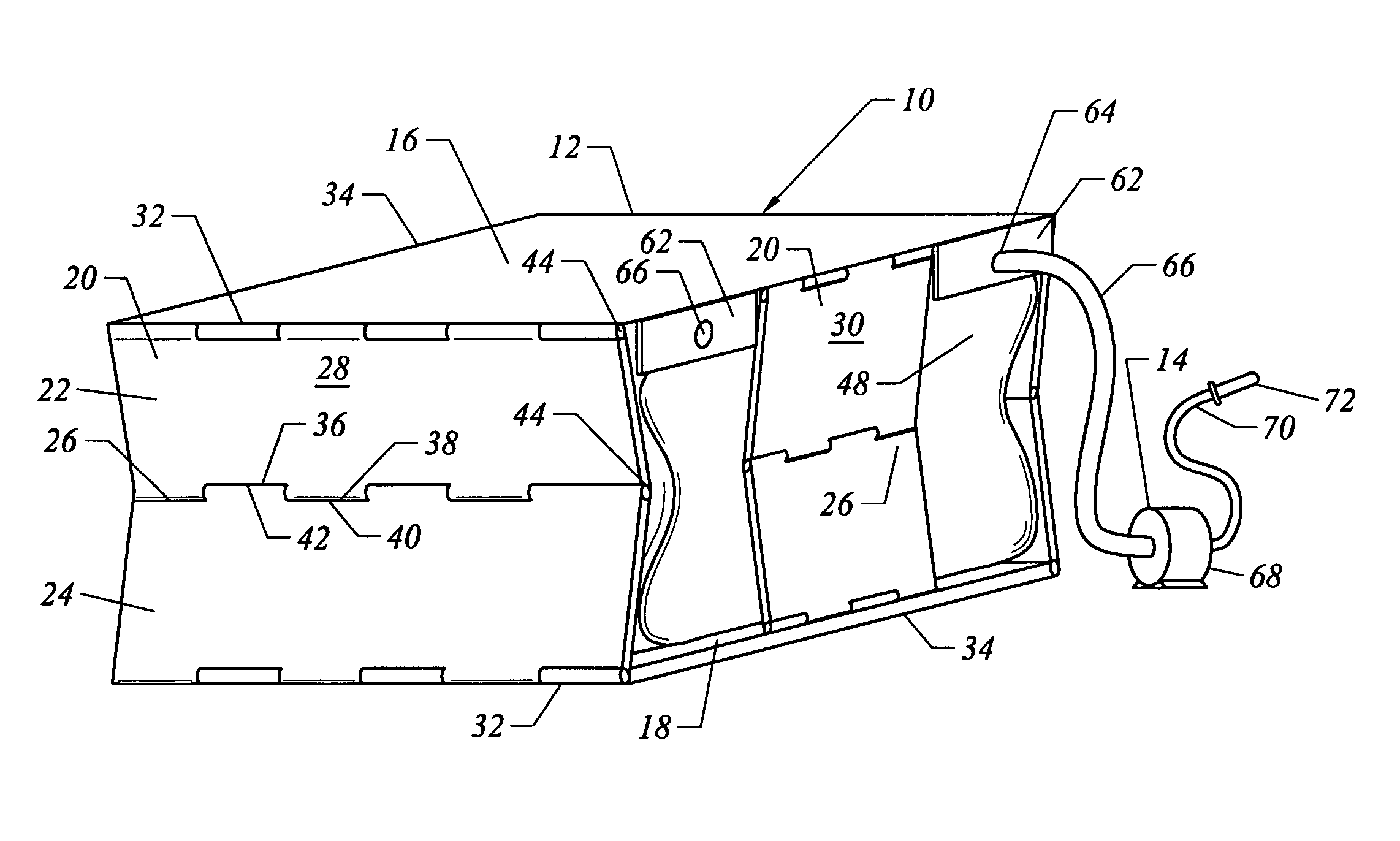
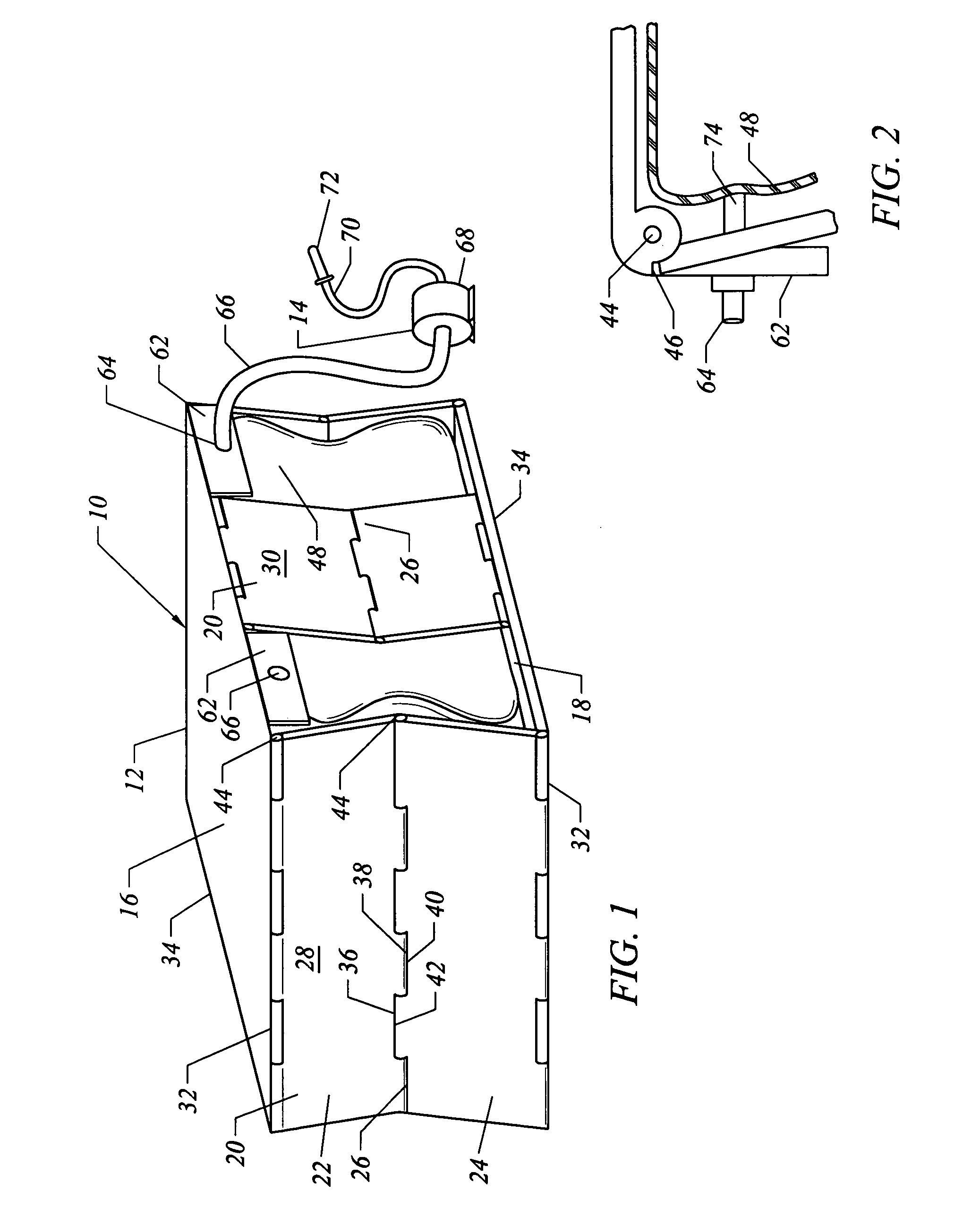
[0021]Referring to FIG. 1, the pneumatic lift device of this invention is designated generally by the reference numeral 10. The pneumatic lift device 10 comprises a lift unit 12 and a pressurized air source 14. In the embodiment of FIG. 1 the lift unit 12 is fabricated of an inexpensive molded plastic with an integral hinge mechanism 15. The lift unit 12 includes a lift platform 16 that is substantially square in configuration and a substantially square base 18. The hinge mechanism 15 interconnects the lift platform 16 and base 18 and includes four foldable side panels 20. The foldable side panels 20 have an upper panel portion 22 and a lower panel portion 24 that are interconnected by a central hinge 26.

[0022]In the embodiment of FIG. 1, two opposed side panels 20 are configured as elongated side panels 28 and the remaining two side panels 20 are configured as narrow side panels 30. The upper and lower panel sections, 22 and 24 of side panels 28 and 30 are connected to the lift pla...


PUM


Abstract

A pneumatic lift device that has a lift unit and an activatable air supply connected to the lift unit with the lift unit having a substantially rectangular base with four sides and a substantially rectangular lift platform connected to the base by a hinge mechanism that includes four foldable side panels connected to the four sides of the base and lift platform with the lift unit having an expandable bladder between the base and lift platform, wherein on expanding the bladder with pressurized air from the air supply, the lift platform rises from the base.

Description

BACKGROUND OF THE INVENTION[0001]This invention relates to a pneumatic lift device that has a simple and inexpensive construction, and, has a variety of common uses. In one preferred embodiment of this invention, the pneumatic lift device is sized and configured for use as an automobile trunk accessory. In another embodiment, the pneumatic lift device is configured as a stand-alone transport dolly. It is to be understood that the preferred embodiments in this specification are set forth for the purpose of aiding in the description and understanding of this invention. The embodiments are not intended to limit the scope of this invention or the variety of different applications to which the invented pneumatic lift device can be applied.[0002]Air lift devices have been constructed in the past for a variety of different uses. Typically, an air lift is of a scissor-type pneumatic jack that is powered by an internal bellows inserted between a lift plate and a base plate. Piston-type air j...

Claims


Application Information

Patent Timeline
IPC IPC(8): B66F3/35B66F3/24
CPCB66F3/35
Inventor KIM, SUN Y.
Owner KIM SUN Y
Why Eureka
Try Eureka