Gas generator

a generator and gas technology, applied in the direction of pedestrian/occupant safety arrangement, vehicular safety arrangement, vehicle components, etc., can solve the problem that the air bag cannot show the inherent function of protecting the driver, and achieve the effect of performing the inherent function of the air bag in safety

Inactive Publication Date: 2005-08-16
NIPPON KAYAKU CO LTD
View PDF20 Cites 38 Cited by
  • Summary
  • Abstract
  • Description
  • Claims
  • Application Information

AI Technical Summary

Benefits of technology

[0026]If the gas generating agents are fired and burned by the eccentric igniters as described above, the combustion is locally generated in the respective combustion chambers. Therefore, in the sixth invention, by varying the permeability of the high-temperature gas, it is possible to distribute the gas throughout the respective combustion chambers and to evenly discharge the clean gas from respective gas discharge ports around the housing even if combustion is locally generated in the respective combustion chambers. In the sixth invention, it is possible to start combustion to the gas generating agent in the vicinity of the eccentric igniters and in a large area around the axis of the housing at a distance from the igniters, so that it is possible to instantaneously shift the combustion to overall combustion. Therefore, it is possible to evenly generate the high-temperature gas by the eccentric igniters around the axis of the housing and to evenly discharge the clean gas around the housing. Furthermore, in the sixth invention, it is possible to actuate the respective igniters at short intervals. By actuating the respective igniters at intervals, it is possible to carry out multistage control of inflation in which the air bag is slowly inflated with a small amount of gas generated in only one combustion chamber in an initial stage of inflation of the air bag and then the air bag is rapidly inflated by adding gas generated in other combustion chambers.
[0027]Therefore, in the sixth invention, the passenger in the driver's seat does not receive an impact caused by rapid deployment and inflation of the air bag in the initial stage of inflation and by uneven deployment of the air bag even if the passenger is seated near the steering wheel. As a result of this, the inherent function of the air bag can be performed in safety.

Problems solved by technology

As a result, there is a problem that the air bag cannot show a inherent function of protecting the driver.

Method used


Image

  • Gas generator
  • Gas generator
  • Gas generator

Examples


Embodiment Construction

[0053]In order to describe the present invention further specifically, the invention will be described according to the accompanying drawings.

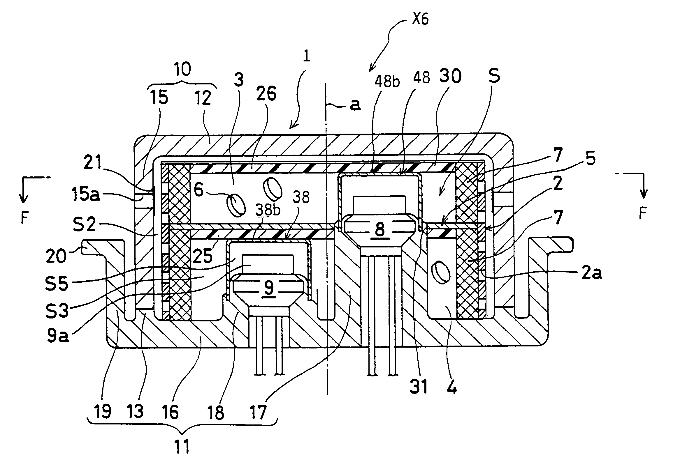
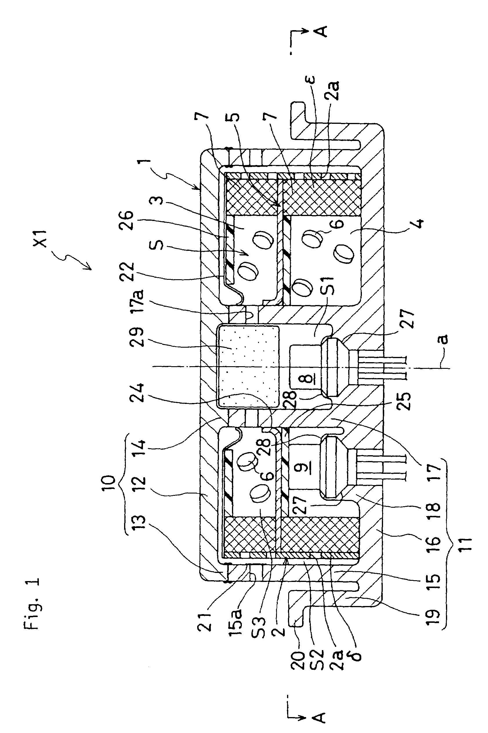
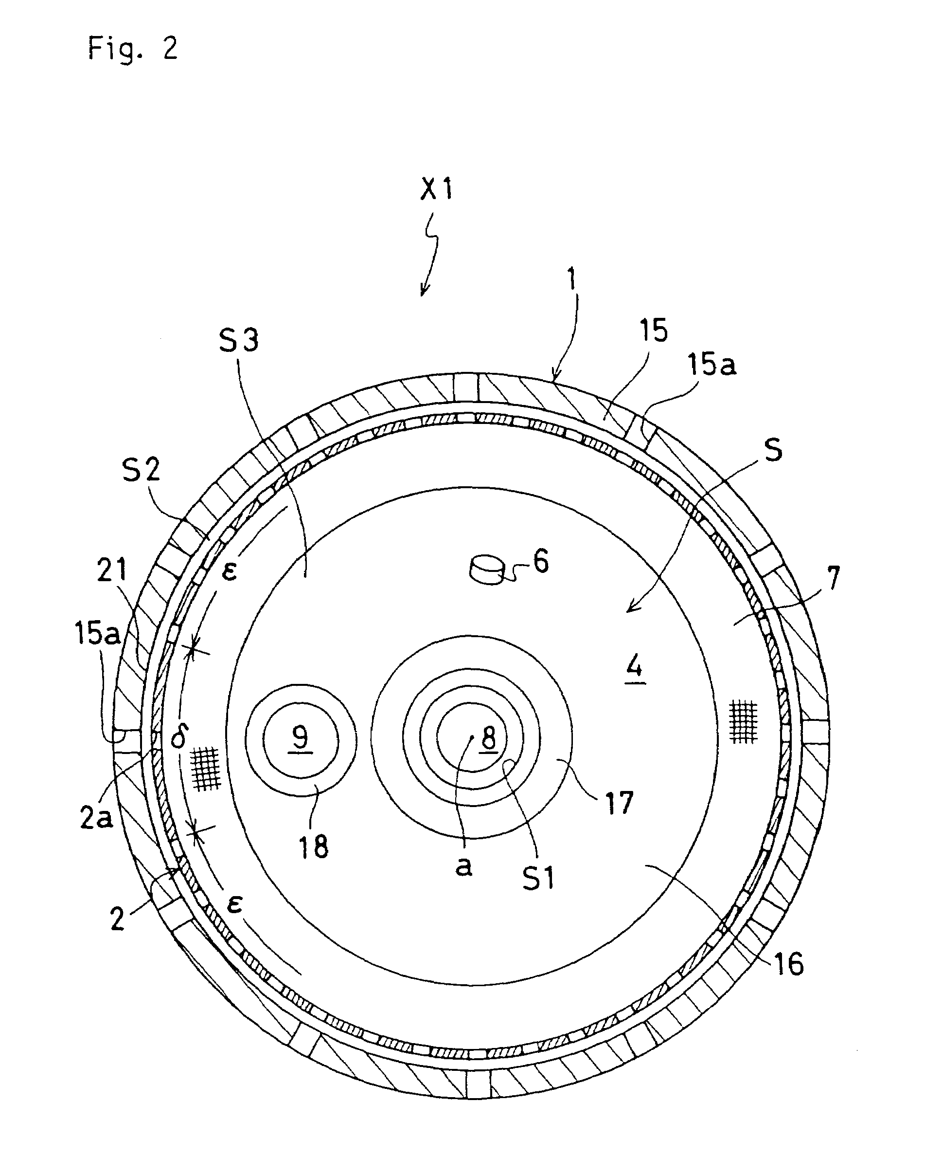
[0054]A gas generator of the invention is mainly used for inflating an air bag for a driver's seat. In the gas generator of the invention, an inside of a housing is partitioned into a plurality of combustion chambers and gas generating agents in each of the combustion chambers are burned by a plurality of igniters, so that a deployment process of the air bag is controllable. In the gas generator of the invention, a clean gas generated by combustion caused by the eccentric igniter is able to evenly discharge from respective gas discharge ports by adopting a structure in which one or more of the respective igniters are disposed eccentrically to an axis of the housing.

[0055]The gas generator used for the air bag for the driver's seat will be described below based on FIGS. 1 to 24.

[0056]The gas generator X1 shown in FIGS. 1 and 2 can control a dep...


PUM


Abstract

A gas generator for slowly inflating an air bag at the early stage of the inflation and then rapidly inflating it or discharge a clean gas evenly around a housing. The gas generator includes a gas generating agent (6) and an squib (8,9) in the housing (1). The squib (9) is disposed eccentrically to the axis (a) of the housing (1). A high temperature gas is generated in a combustion chamber (4) because of the combustion of the gas generating agent (6) ignited by the squib (9). The permeability of the high temperature gas through inner cylindrical member (2) closest to the squib (9) is lower than that through the part other than the inner cylindrical member (2).

Description

TECHNICAL FIELD[0001]The present invention relates to a device for inflating an air bag for an automobile and particularly to a gas generator for controlling a deployment process of the air bag.BACKGROUND TECHNIQUE[0002]A gas generator for rapidly inflating an air bag so as to protect a driver and etc, from an impact caused in a collision of the automobile, is incorporated into an air bag module mounted in a steering wheel. This gas generator instantaneously generates a large amount of high-temperature gas in response to a collision detection signal of a collision sensor in the event of collision.[0003]As one example of the gas generator for inflating the air bag, there is one shown in FIG. 25. This gas generator includes a housing 100, formed by an upper case 101 and a lower case 102 of a double cylindrical structure of having lids. The housing 100 has a structure in which an annular airtight space S is formed in the inside, by abutting and friction-welding at inner cylindrical por...

Claims


Application Information

Patent Timeline
Patent Type & Authority Patents(United States)
IPC IPC(8): B60R21/26B60R21/263B60R21/264
CPCB60R21/2644B60R2021/2633B60R2021/2648B60R21/26B60R21/272
Inventor SASO, TAKASHITANAKA, KOJI
Owner NIPPON KAYAKU CO LTD
Why Eureka
Try Eureka