Journal bearing and thrust pad assembly

a thrust pad and bearing technology, applied in the direction of couplings, manufacturing tools, gear boxes, etc., can solve the problems of premature replacement of prematurely worn bearings, accelerated localized wear of roller elements and bearing races, and equipment shut down

Active Publication Date: 2005-08-16
PRIMETALS TECH USA
View PDF9 Cites 28 Cited by
  • Summary
  • Abstract
  • Description
  • Claims
  • Application Information

AI Technical Summary

Benefits of technology

[0007]In accordance with the present invention, the conventional roller thrust bearings are replaced by combinations of sleeve bearings and thrust ring assemblies. The sleeve bearings provide radial support for the gears in both the engaged and disengaged modes of operation. The thrust ring assemblies absorb axial loads under static conditions when the gears are fixed with respect to their support shafts.

Problems solved by technology

However, when in the engaged mode, the gears are fixed with respect to their support shafts and are subjected to axial loading incidental to the driving forces being delivered to or received from other gears.
It has now been determined, however, that when the gears are fixed with respect to their support shafts in the engaged mode, and the bearings are thus in a static condition, the axial loading on the gears causes the roller elements and races of the bearings to undergo accelerated localized wear in the regions where they are in frictional contact with one another.
This localized wear eventually creates clearances which exceed acceptable tolerances, causing vibrations and necessitating a shut down of the equipment and replacement of the prematurely worn bearings.

Method used


Image

  • Journal bearing and thrust pad assembly
  • Journal bearing and thrust pad assembly
  • Journal bearing and thrust pad assembly

Examples


Embodiment Construction

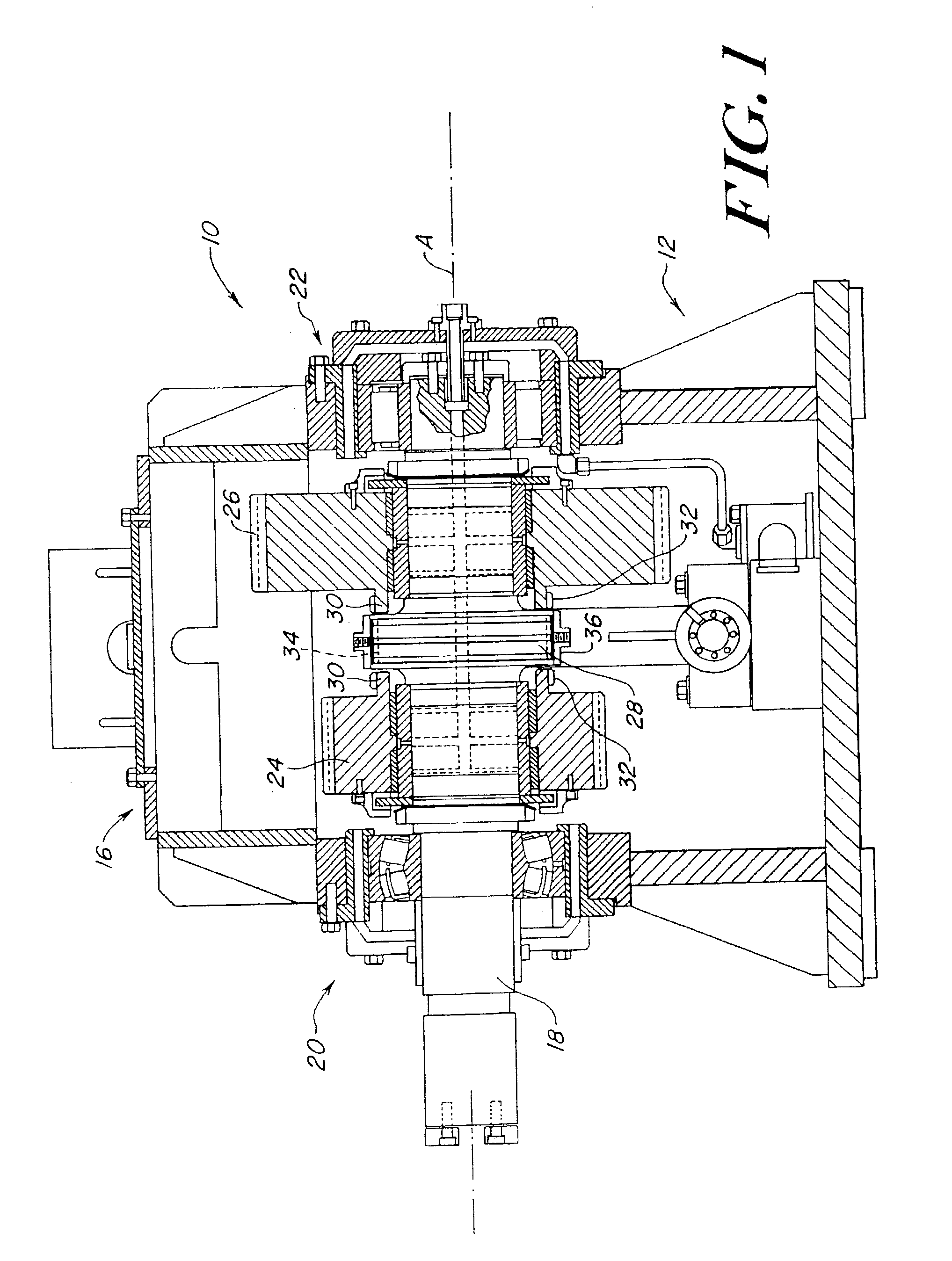
[0016]With reference initially to FIGS. 1, 2, 3A and 3B, a rolling mill gear box is shown at 10. The gear box includes a housing having a base section 12 and cover 16. A shaft 18 is mounted in the housing between bearings 20, 22 for rotation about an axis “A”. One end of the shaft protrudes from the housing for connection to a mill drive (not shown).

[0017]Gears 24, 26 are carried on the shaft on opposite sides of an enlarged diameter shaft collar 28. The gears have different diameters and numbers of teeth, and are thus capable of meshing with other mating gears in the gear box (not shown) to accommodate different drive ratios.

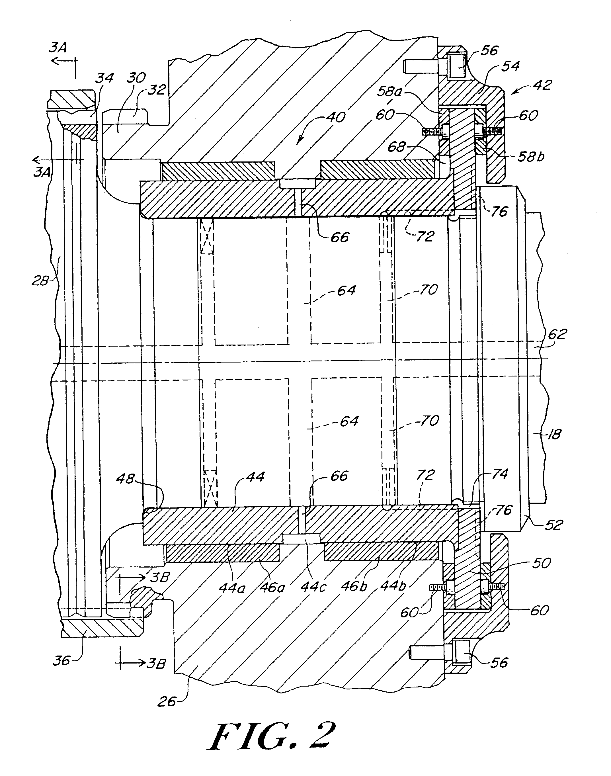
[0018]The gears 24, 26 are each provided with clutch collars 30 having teeth 32 which may be rotatably aligned with external splines 34 on the shaft collar 28. A sleeve 36 internally splined as at 37 is mounted on the shaft collar 28. Sleeve 36 is axially shiftable between a neutral position as shown in FIG. 1 and the upper portion of FIG. 2 and FIG. 3A, and an...


PUM

PropertyMeasurementUnit
pressureaaaaaaaaaa
driving forcesaaaaaaaaaa
rotationaaaaaaaaaa

Abstract

An apparatus for rotatably mounting and axially fixing a gear on a shaft comprises a bushing fixed within a bore of the gear. A sleeve is received on and fixed relative to the shaft. The sleeve is surrounded by and journalled for rotation within the bushing. A thrust ring is fixed relative to and projects radially from the shaft on one side of the gear. A retainer on the one side of the gear defines a circular channel within which the annular thrust ring is axially confined.

Description

[0001]This application claims benefit of 60 / 371,959 filed Apr. 11, 2002.BACKGROUND OF THE INVENTION[0002]1. Field of the Invention[0003]This invention relates generally to heavy duty gear boxes of the type found in the drive trains of rolling mills, where clutches are employed to alternatively engage and disengage gears from their respective support shafts, and is concerned in particular with the bearing assemblies for mounting the gears on the shafts.[0004]2. Description of the Prior Art[0005]In arrangements of the type referred to above, when the gears are disengaged, they are free to rotate or “free wheel” with respect to their support shafts. However, when in the engaged mode, the gears are fixed with respect to their support shafts and are subjected to axial loading incidental to the driving forces being delivered to or received from other gears.[0006]In the past, roller thrust bearings have been employed to mount the gears on their respective support shafts. The roller thrust ...

Claims


Application Information

Patent Timeline
Patent Type & Authority Patents(United States)
IPC IPC(8): F16C33/04F16C33/10F16C17/00F16C17/04F16C17/10B21B31/07F16C17/02B21B35/12F16D1/06F16H3/08F16H57/021F16H57/022
CPCF16C17/10F16C33/1075F16C17/047F16H3/08F16H57/021F16H2200/0034F16C21/00F16C2361/61F16C17/04
Inventor TITUS, DAVID G.
Owner PRIMETALS TECH USA
Why Eureka
Try Eureka