Method and apparatus for blocking pathways between a power cable and the environment

a technology of power cables and pathways, applied in the direction of coupling devices, packaging goods, liquid bottling, etc., can solve the problems of degrading or destroying the injection elbow, causing the danger of an indirect electrical connection being established between the conductor and the grounded exterior of the elbow,

Inactive Publication Date: 2005-08-16
NOVINIUM LLC
View PDF8 Cites 10 Cited by
  • Summary
  • Abstract
  • Description
  • Claims
  • Application Information

AI Technical Summary

Benefits of technology

[0008]One embodiment of the present invention is directed towards a method and apparatus for creating a barrier after the injection of remediation fluid to block the conductive pathway between the conductive portion of an energized cable and the ground plane. An injection elbow with an injection port is used to introduce remediation fluid into the energized cables. The remediation fluid is introduced into the injection port by way of an injection plug inserted into the injection port. Upon completion of the introduction of the remediation fluid, an insulation material is injected through an injection tube of the injection plug and into the injection port. This insulation material may be any of a variety of dielectric, high-viscosity fluids. The insulation material effectively blocks the conductive pathway between the conductive portion of the cable and the ground plane so as to allow removal of the injection plug without creation of a conductive pathway to allow for the insertion of a permanent plug to block the injection port and protect the injection elbow from degradation.
[0009]In another embodiment of the present invention, the injection elbow includes a flap valve located between the injection port and a fluid chamber inside the injection elbow. As fluid is introduced through the injection port, the flap valve is opened either by the fluid pressure, or by an extension on the injection plug, allowing the fluid to fill a chamber in the injection elbow. When the chamber in the fluid elbow is full and introduction of the fluid has ceased, the pressure from inside the chamber forces the flap valve to shut, thus creating a barrier between the conductor and the ground plate. The injection plug can now be removed without exposing the energized conductor which may create a degradation of the injection elbow.
[0010]In still another embodiment of the present invention, a physical barrier is incorporated in the injection plug to block the escape of remediation fluid upon discontinuing filling of the chamber of the injection elbow. This embodiment permits leaving behind the injection plug in the injection port thus eliminating a need for a permanent plug. The physical barrier of this embodiment includes a ball valve; however, a variety of gate valves or check valves, actuated manually, electronically, hydraulically, or pneumatically may be used.

Problems solved by technology

Because of the remediation fluid's low viscosity it is likely to empty out of the open injection port.
Although there is no direct electrical connection between the conductor and the grounded exterior of the cable elbow, there is the danger of an indirect electrical connection being established between the conductor and the grounded exterior of the elbow.
These two known conductive pathways, as well as any other conductive pathway established between the conductor and the ground plane, can degrade or destroy the injection elbow.

Method used


Image

  • Method and apparatus for blocking pathways between a power cable and the environment
  • Method and apparatus for blocking pathways between a power cable and the environment
  • Method and apparatus for blocking pathways between a power cable and the environment

Examples


Embodiment Construction

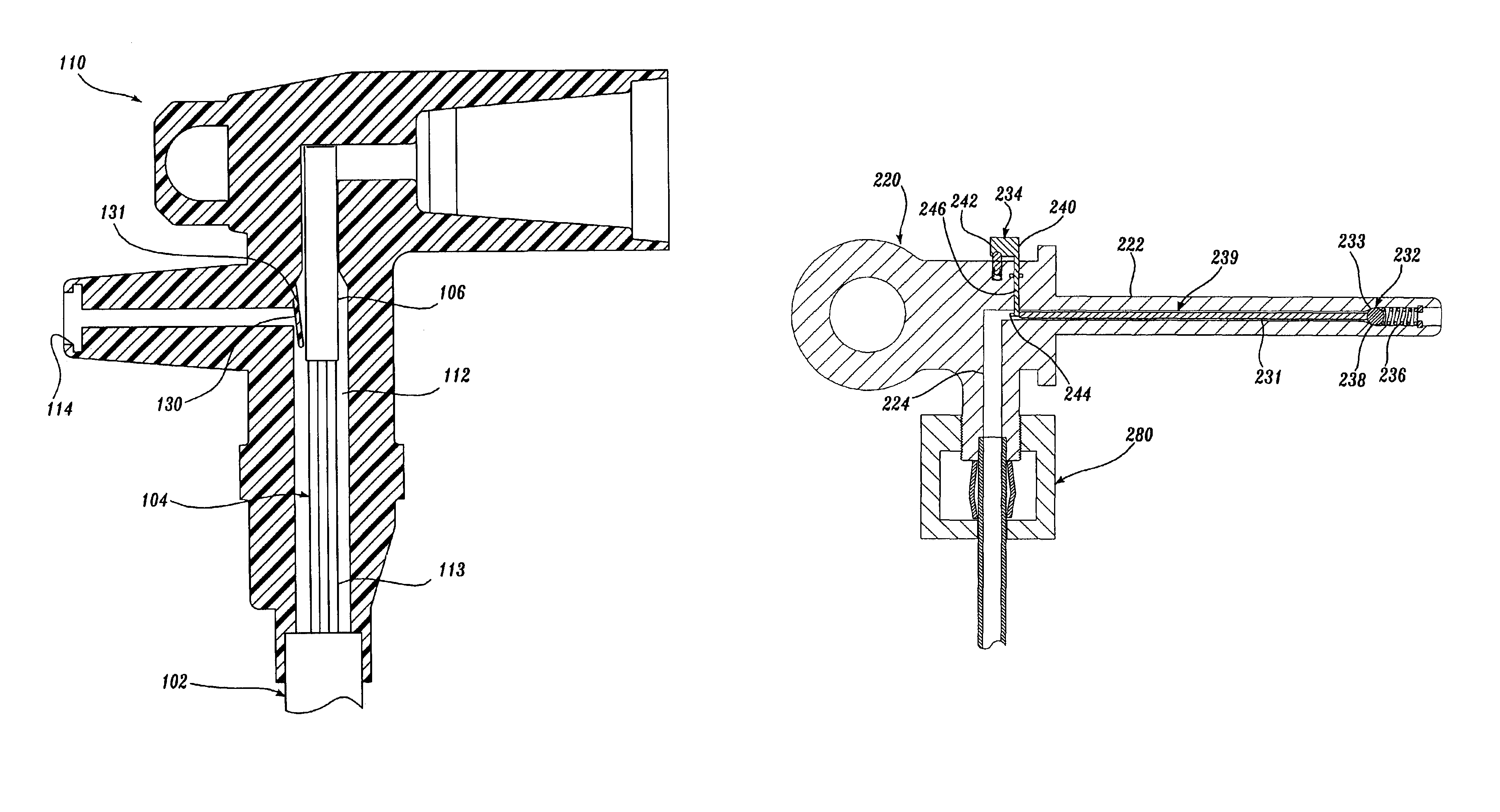
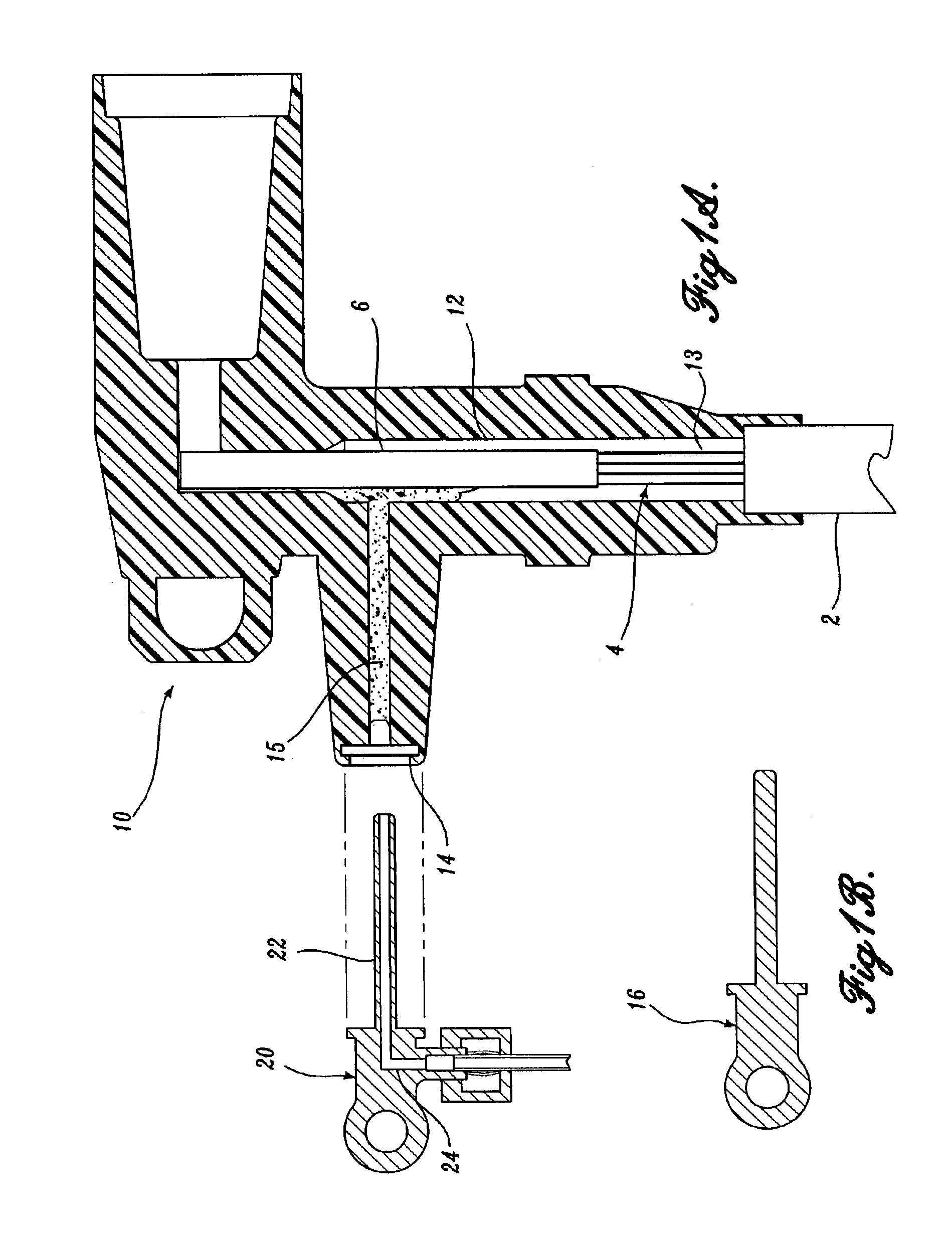
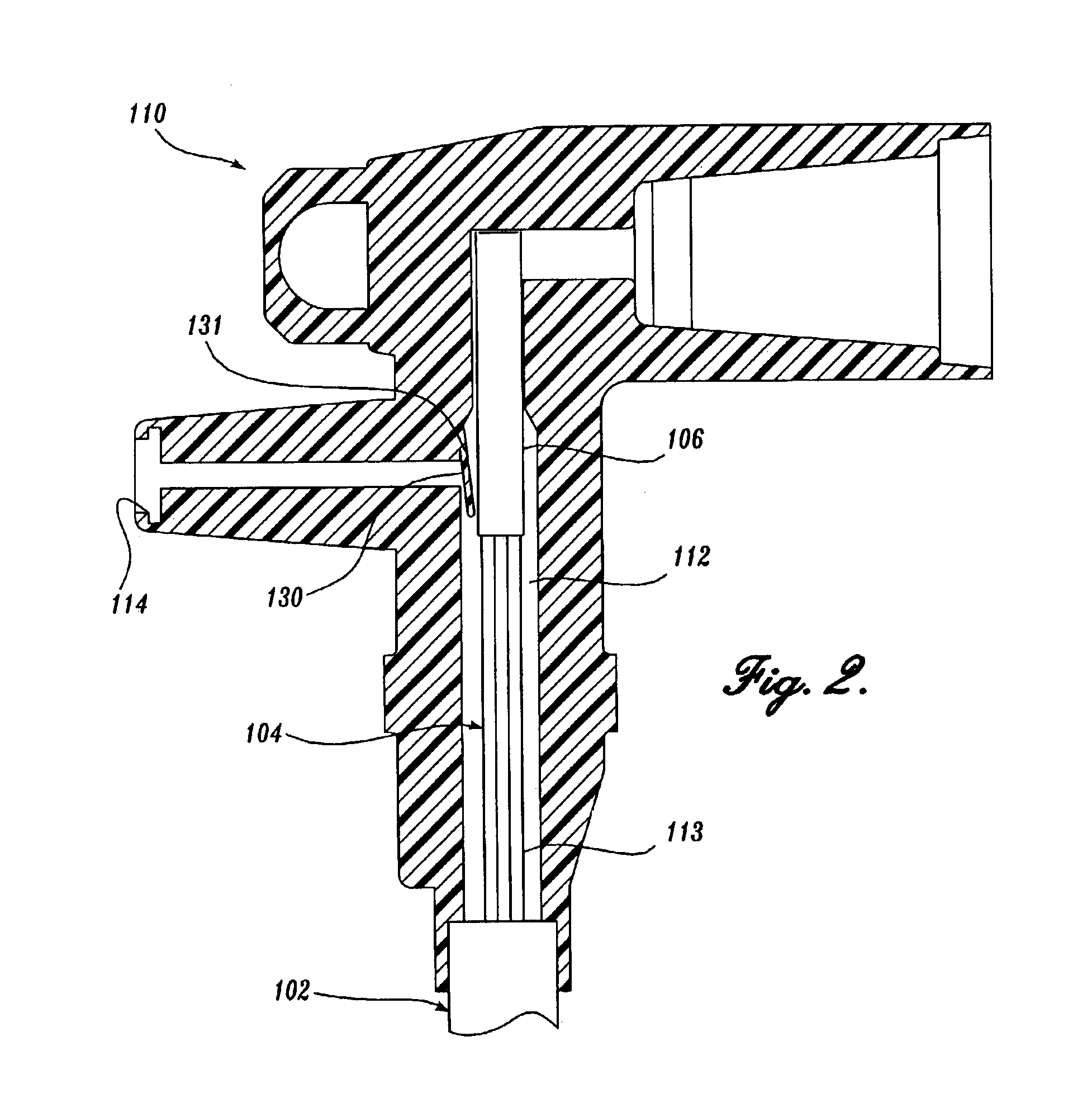
[0018]FIGS. 1A and 1B illustrate an injection elbow 10 formed in accordance with one embodiment of the present invention. Such an injection elbow 10 is adapted to introduce dielectric enhancement fluid into a section of power cable 2, such as a high-voltage electric cable. Typical power cables 2 include a conductive core 4 surrounded by an insulation layer 6. The conductive core 4 includes a plurality of electrically conductive strands 13. Although a plurality of conductive strands 13 is preferred, a cable 2 having a single conductive strand is also within the scope of the present invention. Further, although the injection elbow 10 is illustrated as a load-break connector, other types of connectors, such as tee-body or splice-type connectors which occur at cable junctions, are also within the scope of the present invention.

[0019]The elbow 10 includes a fluid chamber 12 and an injection port 14. The injection port 14 permits the introduction of the dielectric enhancement fluid into t...


PUM

PropertyMeasurementUnit
dielectric strengthaaaaaaaaaa
angleaaaaaaaaaa
fluidic pressureaaaaaaaaaa

Abstract

A cable connector, connector apparatus and method for introducing fluid to a cable. The cable connector, connector apparatus and method configured to form an electrically resistive barrier between components internal to the connector and the environment surrounding the connector after the introduction of the fluid. In one embodiment, a connector comprises a chamber adapted to affix a cable internal to the chamber, wherein the chamber is in fluidic communication with an injection port. The connector further comprises a valve operable to restrict fluid from entering the injection port from the chamber when a fluid source discontinues the introduction of fluid into the injection port. In another embodiment, a method of the present invention involves the application of an insulating material into an injection port of a connector following the application of a dielectric fluid, thereby forming an electrically resistive barrier between components internal to the connector and the external environment.

Description

CROSS-REFERENCE TO RELATED APPLICATION[0001]This application is a continuation of U.S. patent application Ser. No. 10 / 013,940, filed on Dec. 6, 2001 now U.S. Pat. No. 6,517,366 which claims the benefit under 35 U.S.C. § 119(e) of U.S. Provisional Application No. 60 / 251,974, filed on Dec. 6, 2000, both titled “Method and Apparatus for Blocking Pathways Between a Power Cable and the Environment,” the subject matter of which is specifically incorporated herein by reference under 35 U.S.C. §§ 120 and 119, respectively.FIELD OF THE INVENTION[0002]The present invention relates to a remediation process for the insulation of power cables and, more particularly, to injection of dielectric enhancement component into the power cable.BACKGROUND OF THE INVENTION[0003]A remediation process for the insulation of high-voltage electrical power cables requires the injection of a remediation fluid into the cables. It is known in the art that remediation fluids which are most effective have viscosities...

Claims


Application Information

Patent Timeline
Patent Type & Authority Patents(United States)
IPC IPC(8): H01R13/52H01R13/53H01R43/00
CPCH01R13/5216H01R13/53H01R24/20H01R43/005H01R2101/00Y10S439/921
Inventor BERTINI, GLEN J.STAGI, WILLIAM R.
Owner NOVINIUM LLC
Why Eureka
Try Eureka