
Lancing device with automatic stick and return

a technology of automatic stick and lancing blade, which is applied in the field of lancing blade, can solve the problems of lancing blade extension, loud slapping or popping noise of certain devices, and the disconcerting sound of certain devices

Inactive Publication Date: 2005-08-16
LIFESCAN IP HLDG LLC
View PDF8 Cites 141 Cited by
  • Summary
  • Abstract
  • Description
  • Claims
  • Application Information

AI Technical Summary

Benefits of technology

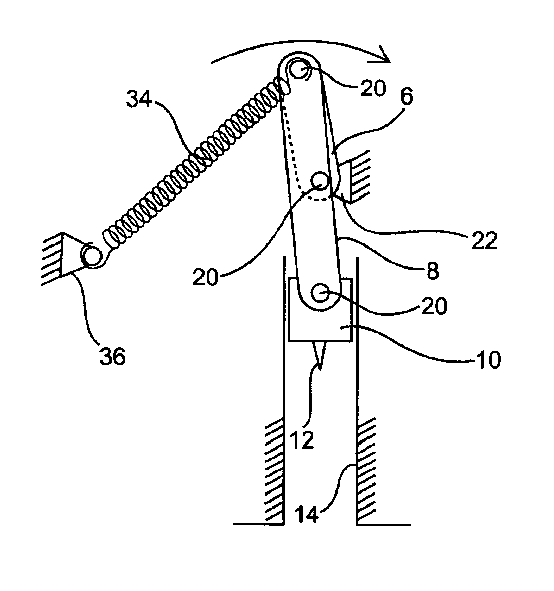
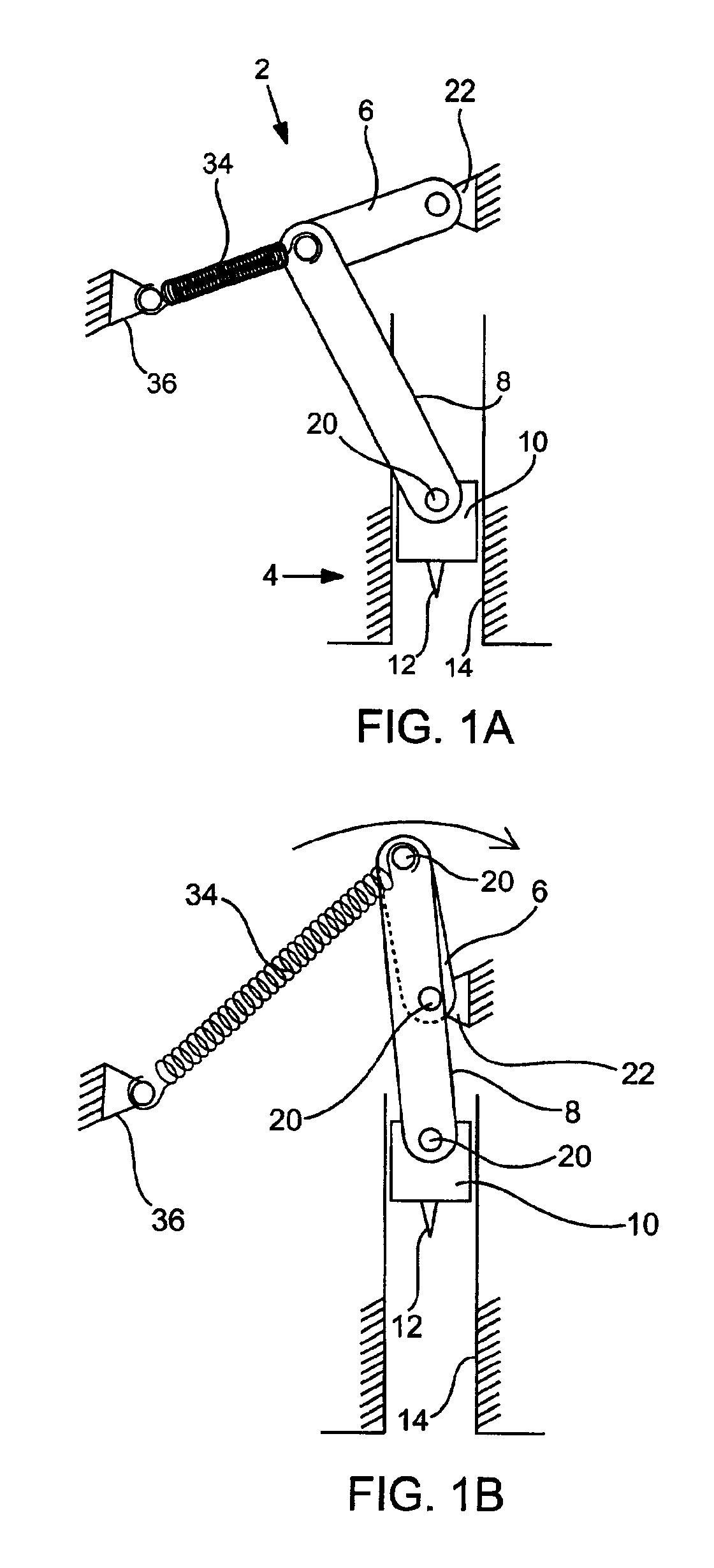
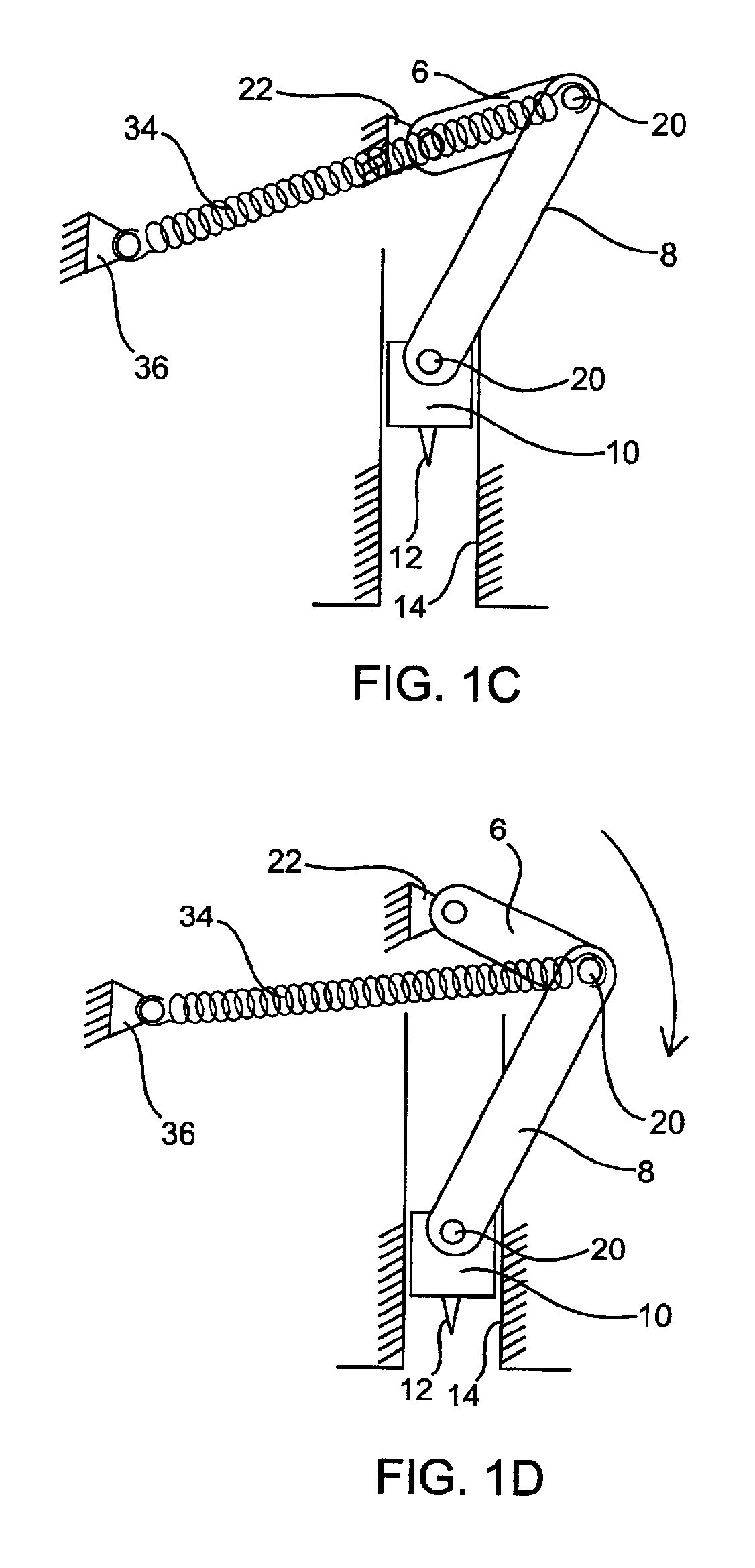
[0010]Prior to cocking the device for firing, the spring preferably sets the position of the lance or lance carrier at a partially retracted position so that a tip of the lance does not pose a safety hazard. The system is preferably configured so that this position substantially coincides with a minimum energy state for the device alleviating risk of lancet misfire. A clutch may be provided in the system, typically at the crank pivot. The drive may be actuated by any number of approaches. However, a ratchet-type mechanism is most preferred.

Problems solved by technology

One such factor contributing to physiological discomfort in using known lancing mechanism results from loud slapping or popping noises certain devices make upon actuation.
Anticipation of the noise or jolting motion of a lancing device can be as disconcerting as the needle stick itself.
A significant disadvantage of this system is presented by the fact that returning the mechanism to a cocked position results in the lance blade extension where it might present a danger in spite of an external housing provided to facilitate finger positioning.
If cocked ahead of time, the system also presents the safety hazard of inadvertent misfire.
The patent fails to disclose further structural details of the actuator.

Method used


Image

  • Lancing device with automatic stick and return
  • Lancing device with automatic stick and return
  • Lancing device with automatic stick and return

Examples


Embodiment Construction

[0017]Before describing variations of the present invention in detail, first, it is to be understood that this invention is not limited to particular variations set forth and may, of course, vary. Various changes may be made to the invention described and equivalents may be substituted without departing from the true spirit and scope of the invention. In addition, many modifications may be made to adapt a particular situation, material, composition of matter, process, process step or steps, to the objective, spirit and scope of the present invention. All such modifications are intended to be within the scope of the claims made herein. Also, it is contemplated that any optional feature of the inventive variations described herein may be set forth and claimed independently, or in combination with any one or more of the features described herein.

[0018]Unless defined otherwise, all technical and scientific terms used herein have the same meaning as commonly understood by one of ordinary...


PUM


Abstract

A lancing device with automatic stick and lance return features is disclosed. A drive mechanism within the unit comprises a slider-crank linkage combination. It is biased by a spring member to cause automatic firing once a crank member advanced by a user causes movement of an internal linkage member beyond its fully-cocked position. After firing, the lance is withdrawn so as not to pose a threat of secondary injury to the user. In use, the device is substantially silent though its course of operation. Yet, its configuration lends itself to producing a very quick, virtually painless stick with minimal recoil or shock to the device.

Description

FIELD OF THE INVENTION[0001]This invention relates to systems for obtaining physiologic fluid samples. More particularly, a lancing device for obtaining blood samples with minimum user discomfort is disclosed.BACKGROUND OF THE INVENTION[0002]Numerous lancing mechanism for obtaining blood samples have been developed. Many of these are optimized for effectiveness in quickly sticking a user with a lancing pin or blade to reduce the sensation of physical pain. Whether intentional or not, others are also designed in a manner that reduces physiological factors associated with obtaining a blood sample.[0003]One such factor contributing to physiological discomfort in using known lancing mechanism results from loud slapping or popping noises certain devices make upon actuation. Another negative stimulus often noticed by users is recoil or sudden motion of the housing of a lancing device associated with lance firing. Anticipation of the noise or jolting motion of a lancing device can be as di...

Claims


Application Information

Patent Timeline
Patent Type & Authority Patents(United States)
IPC IPC(8): A61B5/15
CPCA61B5/1411A61B5/150022A61B5/150358A61B5/150412A61B5/150503A61B5/15113A61B5/15117A61B5/15128A61B5/1519A61B5/15194
Inventor PUGH, JERRY T.
Owner LIFESCAN IP HLDG LLC
Learn More