Three dimensional MRI RF coil unit capable of parallel imaging

a three-dimensional, parallel imaging technology, applied in the field of signal detection rf coils, can solve problems such as difficult application of pi methods

Inactive Publication Date: 2005-08-16
TOSHIBA MEDICAL SYST CORP
View PDF24 Cites 45 Cited by
  • Summary
  • Abstract
  • Description
  • Claims
  • Application Information

AI Technical Summary

Benefits of technology

[0026]FIG. 12 is a view for explaining the effect of this magnetic resonance imaging apparatus;
[0027]FIG. 13 is a view for explaining the effect of this magnetic resonance imaging apparatus;

Problems solved by technology

However, conventional magnetic resonance imaging apparatuses are not designed to arrange RF coils in the three directions, i.e., the X, Y, and Z directions, but are designed to arrange RF coils in the two directions, i.e., the X and Y directions or the Y and Z directions.
Furthermore, when a slice in an arbitrary direction (oblique imaging) is selected, the PI method is difficult to apply.

Method used


Image

  • Three dimensional MRI RF coil unit capable of parallel imaging
  • Three dimensional MRI RF coil unit capable of parallel imaging
  • Three dimensional MRI RF coil unit capable of parallel imaging

Examples


Embodiment Construction

[0031]An embodiment of the present invention will be described below with reference to the views of the accompanying drawing. Note that the same reference numerals denote constituent elements having substantially the same functions and arrangements, and a repetitive description will be made only when required.

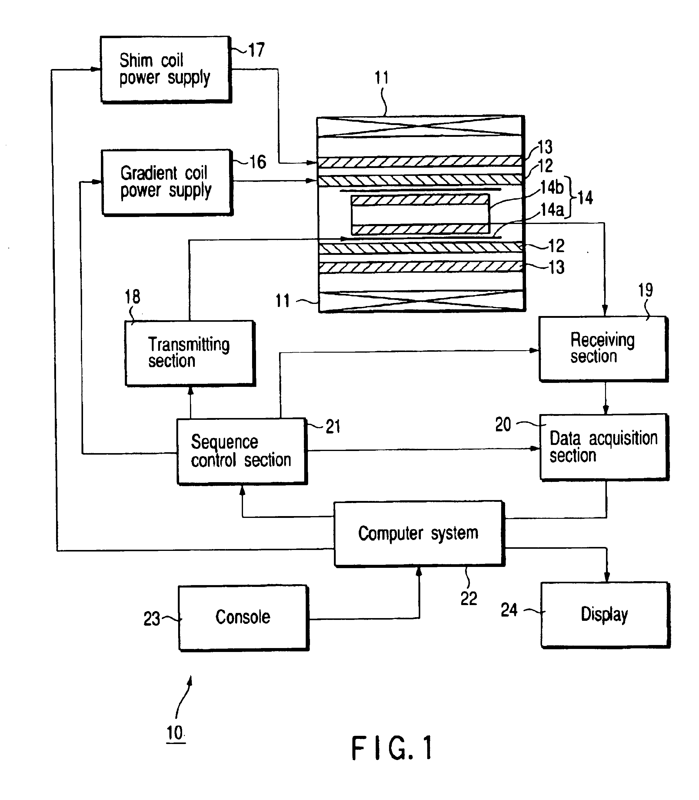
[0032]FIG. 1 is a block diagram showing the arrangement of a magnetic resonance imaging apparatus according to this embodiment. Referring to FIG. 1, a magnetic resonance imaging apparatus 10 includes a static magnetic field magnet 11, gradient coil 12, shim coil 13, RF coil 14, gradient coil power supply 16, shim coil power supply 17, transmitting section 18, receiving section 19, data acquisition section 20, sequence control section 21, computer system 22, console 23, and display 24.

[0033]The static magnetic field magnet 11 is a magnet for generating a static magnetic field. This magnet generates a uniform static magnetic field. As the static magnetic field magnet 11, a perman...


PUM


Abstract

A magnetic resonance imaging apparatus acquires magnetic resonance signals by the PI method using an RF coil unit having basic coils serving as surface coils which are arrayed with at least two coils along a static magnetic field direction (z direction) and at least two coils along each of two orthogonal x, y directions. The coils are divided into an upper unit and a lower unit. The upper unit and lower unit are fixed by a band or the like to allow them to be mounted on an object to be examined. The signals detected by the respective surface coils are sent to a data processing system through independent receiver units and formed into a magnetic resonance image.

Description

CROSS-REFERENCE TO RELATED APPLICATIONS[0001]This application is based upon and claims the benefit of priority from the prior Japanese Patent Application No. 2001-358372, filed Nov. 22, 2001, the entire contents of which are incorporated herein by reference.BACKGROUND OF THE INVENTION[0002]1. Field of the Invention[0003]The present invention relates to a signal detection RF coil which generates a magnetic resonance signal by applying RF pulses to an object to be examined in a static magnetic field and at the same time, acquires a magnetic resonance signal, and a magnetic resonance imaging apparatus which using the RF coil.[0004]2. Description of the Related Art[0005]A magnetic resonance imaging (MRI) apparatus is an apparatus which images the chemical and physical microscopic information of a substance by using a phenomenon in which when a group of nuclei having a unique magnetic moment is placed in a uniform static magnetic field, they resonantly absorb energy of an RF magnetic fie...

Claims


Application Information

Patent Timeline
Patent Type & Authority Patents(United States)
IPC IPC(8): G01R33/3415G01R33/34G01R33/341A61B5/055G01V3/00
CPCG01R33/3415G01R33/3678
Inventor OKAMOTO, KAZUYAHAMAMURA, YOSHINORIMACHIDA, YOSHIO
Owner TOSHIBA MEDICAL SYST CORP
Why Eureka
Try Eureka