Sensor front-end with phase coding capability

a technology of phase coding and sensor, which is applied in the direction of instruments, measurement devices, and using reradiation, etc., can solve the problems of high mass, high cost, and stringent requirements of the system that utilizes these sensors

Active Publication Date: 2005-08-16
VEONEER US LLC
View PDF10 Cites 16 Cited by
  • Summary
  • Abstract
  • Description
  • Claims
  • Application Information

AI Technical Summary

Problems solved by technology

The requirements of the systems that utilize these sensors are often quite stringent both in terms of performance and in the physical and economic factors as well.
The more complex the sensor, the larger the parts count, and concomitantly, the higher the cost, the higher the mass, the larger the physical volume of the sensor and the lower the reliability of the sensor.

Method used


Image

  • Sensor front-end with phase coding capability
  • Sensor front-end with phase coding capability
  • Sensor front-end with phase coding capability

Examples


Embodiment Construction

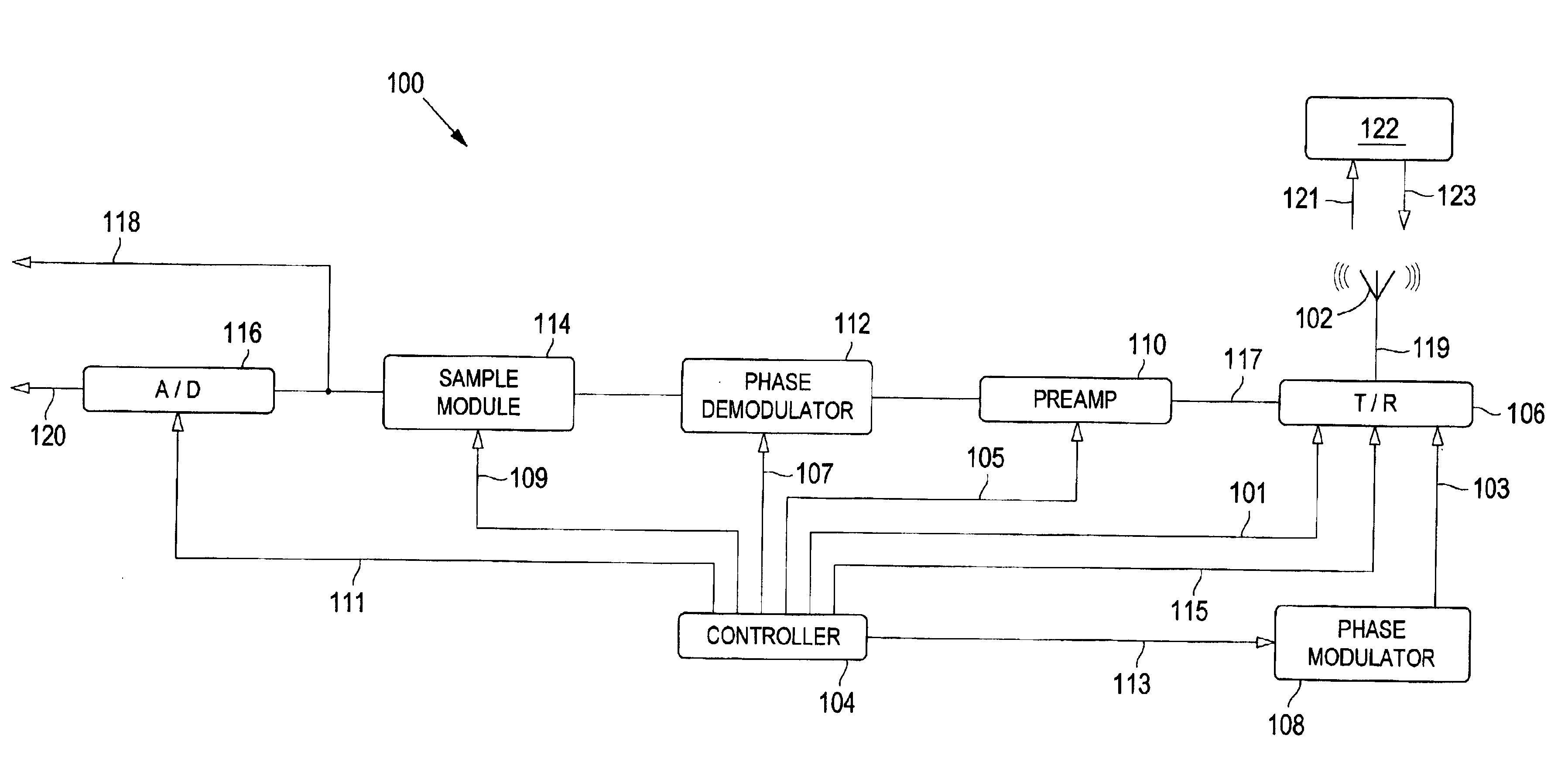
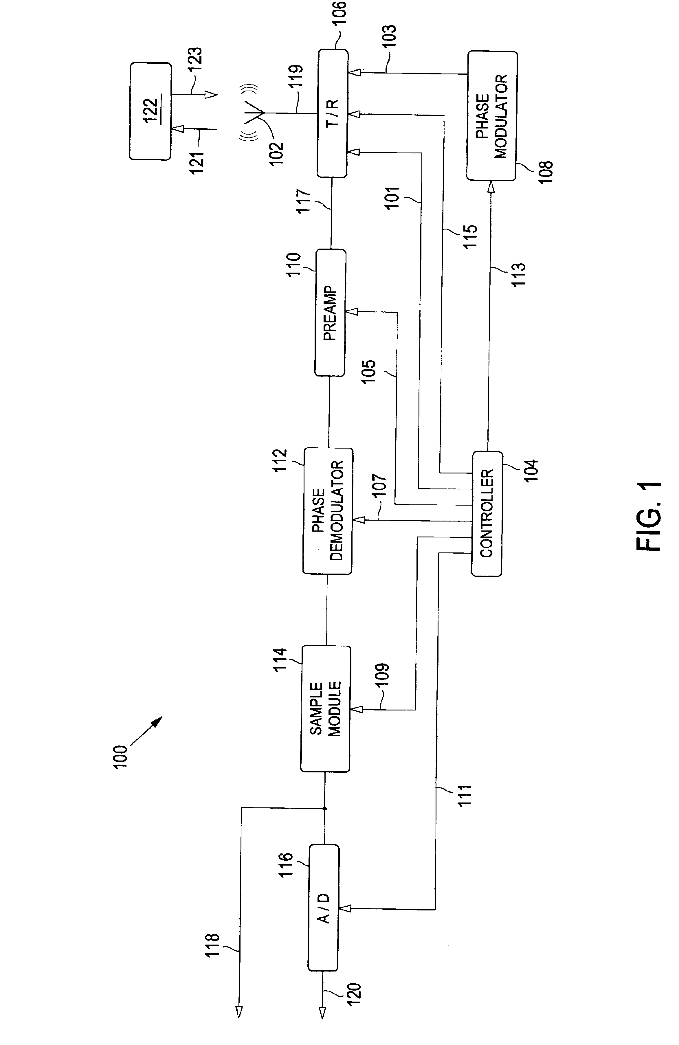
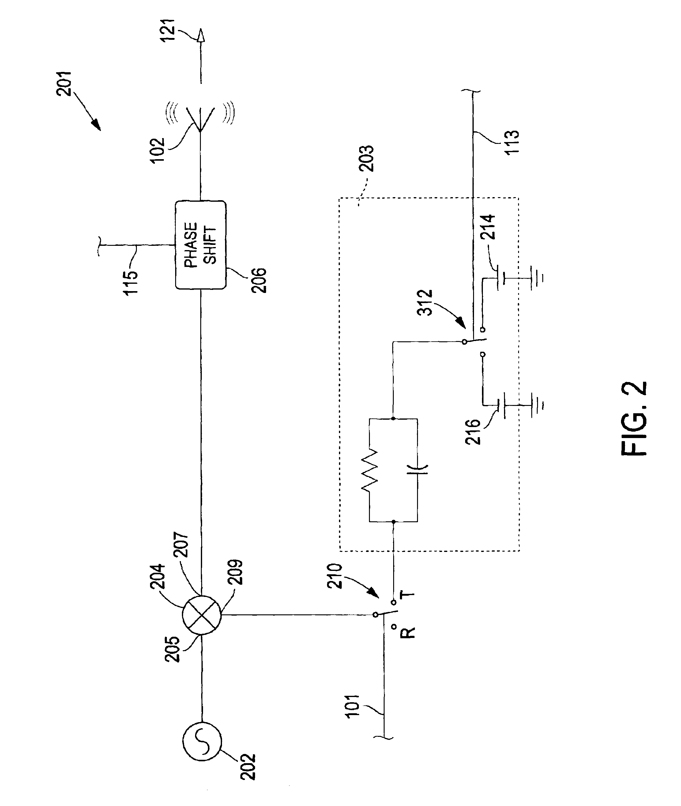
[0020]FIG. 1 depicts a block diagram of the architecture of a sensor front end consistent with the present invention. FIGS. 2 and 3 depict the transmitter functions including a phase-modulator and the receiver functions including phase code demodulator respectively. FIGS. 4-9 depict circuits suitable for use in the sensor front depicted in FIGS. 1-3, and FIG. 10 depicts another embodiment of the sensor front end. Although the following embodiments are described with respect to microwave frequencies and components, the apparatus and methods described herein may be applied to other frequencies and systems.

[0021]As depicted in FIG. 1, a controller 104 provides a plurality of control signals to ensure the proper timing and operation of the various components in the sensor front end 100. The sensor front end 100 includes a transceiver 106 that can simultaneously transmit a phase-modulated sensor signal 121 from an antenna 102 and coherently receive a reflected signal 123 and down convert...


PUM


Abstract

A sensor front end for an electronic radar sensor is disclosed that provides for a lower parts count while providing technical functionality by using multifunction parts, i.e., parts that are used both in transmitting and receiving. The sensor front end includes a continuous wave signal source that functions as a signal source when the front end is transmitting a signal and as a local oscillator when the front end is receiving a signal. The sensor front end also includes a tri-mode mixer that functions as a phase-modulator and transmit switch when the front end is transmitting a signal and as a mixer/down-converter when the front end is receiving a signal. The sensor front end further includes a common aperture antenna that acts as both a transmitting antenna for transmitting a sensor signal and for receiving a reflected signal from a object. A phase shifter can be added to provide a predetermined phase shift in the transmitted sensor signal, the received reflected signal, or both, such that in-phase and quadrature signal components are provided. In addition, phase coding may be added to the signal to reduce the degenerative impact of interfering signals. A receiver module is coupled to the tri-mode mixer such that, when receiving a reflected signal, the receiver provides a baseband sensor output signal that can be used to determined the position and velocity of the object. A sampling module can be added such that the sensor output signal is sampled and provided as an analog signal, or the sampled sensor output signal can be provided to an analog-to-digital converter to convert the sensor output signal into a digital format, or both.

Description

CROSS REFERENCE TO RELATED APPLICATIONS[0001]N / ASTATEMENT REGARDING FEDERALLY SPONSORED RESEARCH OR DEVELOPMENT[0002]N / ABACKGROUND OF THE INVENTION[0003]Proximity sensors of various types are used in a variety of applications in which the distance to an object and, in some circumstances, the closing velocity of that object are to be determined. This data is often provided to a processing system for analysis. Typically, this analysis determines whether one or both of the distance and velocity exceed a predetermined safety threshold and whether an alarm is to be set or other action taken. Proximity sensors are used, for example, in a variety of applications that can include burglar alarms, obstacle detection, and automobiles. Proximity sensors in automobiles are used to determine the relative position and closing velocity of other automobiles or objects in the vicinity of the automobile. These sensors must be physically small, light weight, highly reliable, and low cost. The requireme...

Claims


Application Information

Patent Timeline
Patent Type & Authority Patents(United States)
IPC IPC(8): G01S7/02G01S7/35G01S13/93G01S13/00G01S7/28G01S13/931
CPCG01S7/352G01S7/023G01S13/931G01S2007/358G01S7/358G01S7/0234G01S13/00
Inventor PUGLIA, KENNETH V.
Owner VEONEER US LLC
Why Eureka
Try Eureka