Device and procedure for aligning of components

a technology for components and devices, applied in the direction of surveying and navigation, gearing control, instruments, etc., can solve the problems of unnecessarily high wear and tear of belts and belt discs, unnecessarily high power consumption, and reduce the degree of efficiency of the machines for which belt discs are used

Inactive Publication Date: 2005-08-23
ACOEM
View PDF16 Cites 32 Cited by
  • Summary
  • Abstract
  • Description
  • Claims
  • Application Information

AI Technical Summary

Benefits of technology

[0014]By means of the invention a number of advantages are obtained. Principally, it may be noted that the invention admits a simple and effective alignment of for example belt discs, which may be performed at a low cost. The receiver unit according to the invention has a simple and compact design and is easy to operate. By in particular using two detectors which are placed in two separate planes perpendicular to the propagation direction of the light pattern, the invention may be used for a simultaneous detection of any present parallel, angular and twist errors. The construction of the receiver unit also enables an absolute determination of these three different types of error, independently of the geometry of the components, for example belt discs, which shall be aligned.

Problems solved by technology

A misalignment of the belt discs may otherwise lead to an unnecessarily high wear of the belts and belt discs and an unnecessarily high power consumption (i.e. a reduced degree of efficiency) of the machines for which the belt discs are used.
Angular error means that those planes along which the belt discs are arranged have a certain angle in relation to each other.

Method used


Image

  • Device and procedure for aligning of components
  • Device and procedure for aligning of components
  • Device and procedure for aligning of components

Examples


Embodiment Construction

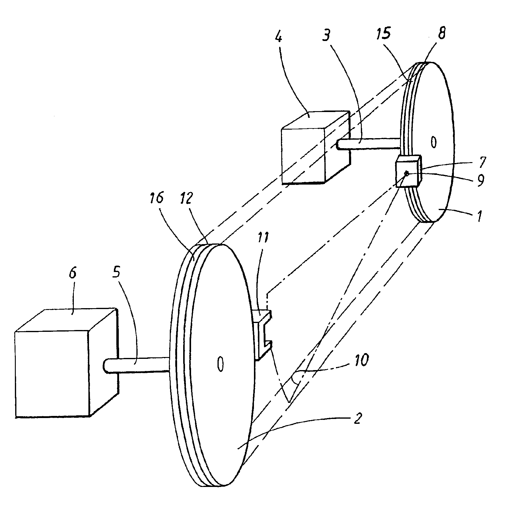
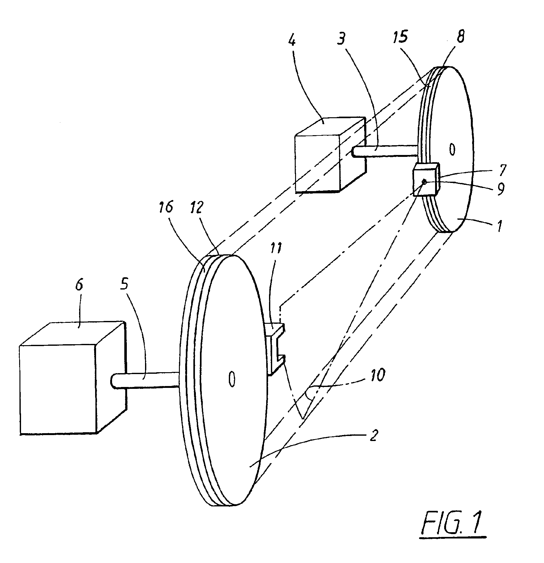
[0027]In FIG. 1 a perspective view of a device according to the present invention is shown. The invention is in particular, but not exclusively, intended to be used at alignment of two power transmitting belt discs 1, 2 in relation to each other, i.e. positioning them along an imaginary common plane, in what way twist, angular and parallel errors between the belt discs 1, 2 are reduced or preferably totally eliminated.

[0028]The invention is suitable to be used at the type of alignment of two components in relation to each other where there is a desire to position these two components along a common plane. In particular, the invention may be used at applications that comprise power transmission by means of rotating transmission devices, for example of the type chain propulsion or belt propulsion, and may then be used e.g. in connection with fan systems or machines.

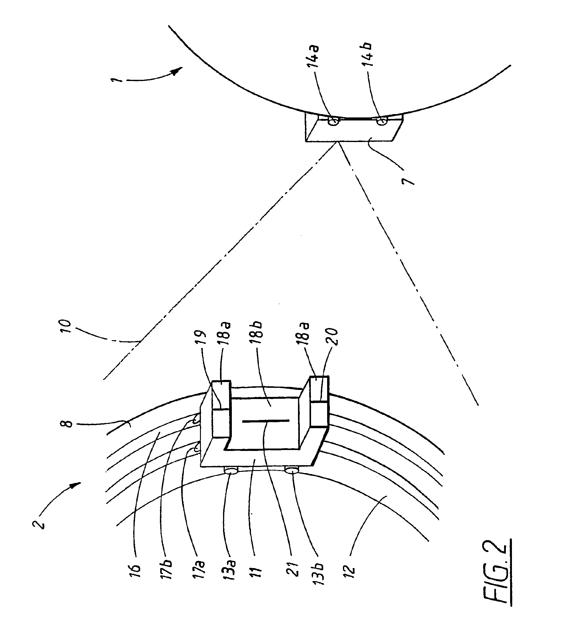
[0029]The invention will in the following be described with reference to FIGS. 1 and 2, which show an embodiment comprisi...


PUM


Abstract

The invention relates to a device for alignment of a first component (1) and a second component (2) in a predetermined relation to each other, comprising a transmitter unit (7) arranged for mounting on said first component (1) and comprising a light source (9) for the generation of light radiation (10) with a predetermined pattern in the direction towards a receiver unit (11; 11′, 22, 27; 27′) arranged for mounting on said second component (2), where the receiver unit (11; 11′) comprises a detection device (18a, 18b; 18a′, 18b′ 23a, 23b; 28a, 28b; 28′a, 28′b) for said light radiation (10). The invention is characterised in that said detector device (18a, 18b; 18a′, 18b′, 23a, 23b; 28a, 28b, 28′a, 28′b) comprises a first detector (18a, 18a′ 23a; 28a; 28a′) and a second detector (18b; 18b′ 23b; 28b; 28′b), respectively, which are separated depthwise in relation to said transmitter unit (7). The invention also relates to a receiver unit (11; 11′; 22, 27, 27′) for the above-mentioned type of alignment, and also a method for such alignment. By means of the invention, an improved alignment of for example belt discs is provided.

Description

TECHNICAL FIELD[0001]The present invention relates to a device for aligning of a first component and a second component in a predetermined relation to each other, comprising a transmitter unit arranged for mounting on said first component and comprising a light source for generation of light radiation with a predetermined pattern in the direction towards a receiver unit arranged for mounting on said second component, where the receiver unit comprises a detector device for said light radiation.[0002]The invention also relates to a receiver unit intended to co-operate with a transmitter unit for aligning of a first component and a second component in a predetermined relation to each other, which receiver unit is arranged for mounting on one of the components and arranged for detection of a light pattern emitted by said transmitter unit.[0003]The invention also relates to a method for aligning of a first component and a second component in a predetermined relation to each other, compri...

Claims


Application Information

Patent Timeline
Patent Type & Authority Patents(United States)
IPC IPC(8): F02B67/06G01B11/27F16H61/66F16H61/662F16H7/24F16H7/00
CPCF02B67/06G01B11/272F16H7/24F16H2061/66295Y10S33/21
Inventor BODGREN, JANSTROMBERG, PETERSANDSTROM, PETERPETERSSON, HENRIK
Owner ACOEM
Why Eureka
Try Eureka