
Cooling system with isolation valve

a technology of isolation valve and cooling system, which is applied in the direction of process and machine control, lighting and heating apparatus, instruments, etc., can solve the problems of significant reduction of the on-cycle evaporator temperature, affecting the performance of the refrigeration system, and increasing the temperature of liquid refrigerant, so as to reduce the deficiencies associated with the effect of temperature ris

Inactive Publication Date: 2005-08-23
COPELAND LP
View PDF6 Cites 24 Cited by
  • Summary
  • Abstract
  • Description
  • Claims
  • Application Information

AI Technical Summary

Benefits of technology

[0008]Accordingly, the present invention provides a refrigeration system and control method thereof, for alleviating the deficiencies associated with traditional refrigeration systems. More particularly, the refrigeration system includes an evaporator, a variable capacity compressor coupled in fluid communication with the evaporator, a condenser coupled in fluid communication between the compressor and the evaporator, an expansion valve disposed intermediate the condenser and the evaporator, and an isolation valve disposed intermediate the condenser and the expansion valve. The isolation valve is in communication with the compressor for respectively synchronizing opening and closing thereof with on- and off-cycles of the compressor to prohibit migration of liquid refrigerant. In this manner, respective temperatures of the condenser and evaporator are better maintained during the off-cycle.
[0009]In accordance with an alternative embodiment, first and second check valves are respectively associated with the compressor and the condenser for prohibiting reverse migration of refrigerant during the off-cycle. In this manner, respective pressures of the refrigerant associated with the condenser and evaporator are decreased over a traditional refrigeration system.
[0010]The present invention further provides a method for controlling a refrigeration system having a compressor, a condenser and an evaporator connected in series flow communication. The method includes the steps of varying the compressor between on- and off-cycles to provide a percent duty cycle thereof, and synchronizing opening and closing of an isolation valve, respectively with the on- and off-cycles of the compressor, to prohibit migration of liquid refrigerant into the evaporator during the off-cycle.
[0011]In accordance with an alternative embodiment, the method further includes the steps of prohibiting reverse migration of the liquid refrigerant into the condenser, and prohibiting reverse migration of vapor refrigerant through the compressor, during the off-cycle.

Problems solved by technology

Heat is transferred from the cooled area to the liquid refrigerant, thereby increasing the temperature of the liquid refrigerant and resulting in boiling thereof.
This is detrimental to the performance of the refrigeration system in two ways: a significant reduction in the on-cycle evaporator temperature, and a decrease in flow recovery once switched back to the on-cycle.
Further, significant losses occur with traditional refrigeration systems when recently compressed vapor reverse migrates through the compressor, back toward the evaporator, during the off-cycle.

Method used


Image

  • Cooling system with isolation valve
  • Cooling system with isolation valve
  • Cooling system with isolation valve

Examples


Embodiment Construction

[0020]The following description of the preferred embodiments is merely exemplary in nature and is in no way intended to limit the invention, its application, or uses.

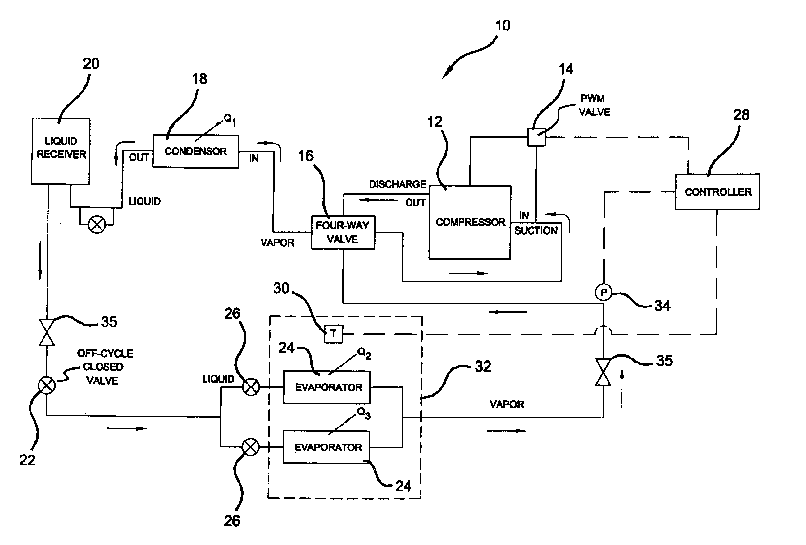
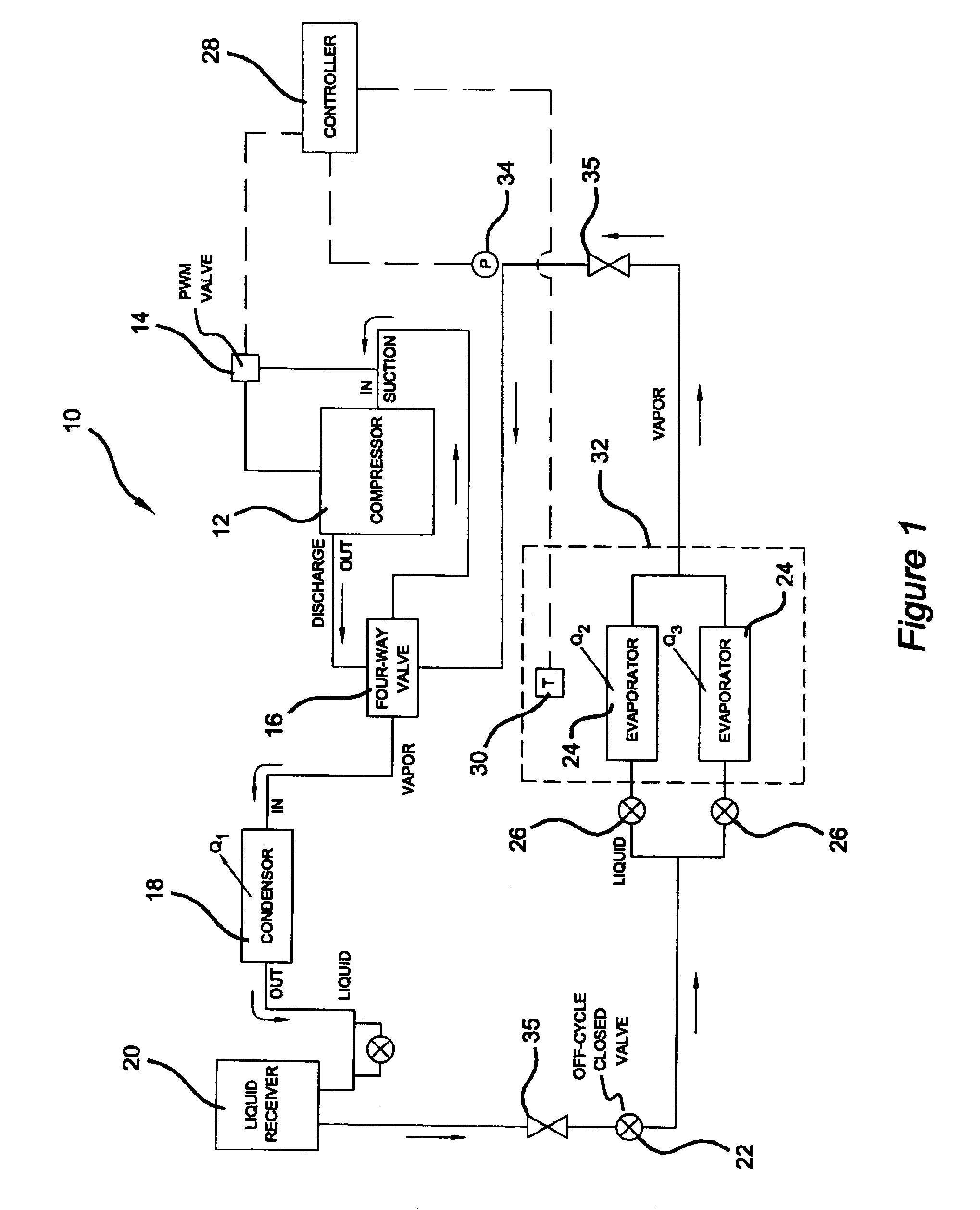
[0021]With particular reference to FIG. 1, a refrigeration system 10 is schematically shown. Although the refrigeration system 10 is representative of a heat pump system, it will be appreciated that the implementation thereof, in accordance with the present invention, is for refrigeration. The refrigeration system 10 includes a compressor 12 having an associated pulse-width modulation (PWM) valve 14, a four-way valve 16, a condenser 18, a liquid receiver 20, an isolation valve 22, dual evaporators 24 having respective expansion valves 26, and a controller 28. The controller 28 is in operable communication with the PWM valve 14 of the compressor 12, a temperature sensor sensing 30 a temperature of a refrigerated area 32 (e.g. interior of a refrigeration case), and a pressure sensor 34 sensing a pressure of a refrigerant ...


PUM


Abstract

A cooling system including a pulse-width modulated variable capacity compressor operable between on-cycles and off-cycles, and in electrical communication with the compressor and operable to respectively synchronize opening and closing thereof with on- and off-cycles of the compressor.

Description

CROSS-REFERENCE TO RELATED APPLICATIONS[0001]This application is a continuation of U.S. patent application Ser. No. 10 / 195,839 filed on Jul. 15, 2002, now U.S. Pat. No. 6,672,090. The disclosure of the above application is incorporated herein by reference.FIELD OF THE INVENTION[0002]The present invention relates to refrigeration systems, compressor control systems and refrigerant regulating valve control systems. More particularly, the invention relates to liquid-side and vapor-side flow control strategies.BACKGROUND OF THE INVENTION[0003]Traditional refrigeration systems include a compressor, a condenser, an expansion valve, and an evaporator, all interconnected for establishing series fluid communication therebetween. Cooling is accomplished through evaporation of a liquid refrigerant under reduced temperature and pressure. Initially, vapor refrigerant is drawn into the compressor for compression therein. Compression of the vapor refrigerant results in a higher temperature and pre...

Claims


Application Information

Patent Timeline
Patent Type & Authority Patents(United States)
IPC IPC(8): F25B49/02F25B41/04F25B1/04
CPCF25B41/04F25B49/022F25B1/04F25B2700/2104F25B2600/0251F25B2700/1933F25B2500/27F25B41/20F25B41/24
Inventor HEALY, JOHN JOSEPHWU, MAN WAING, MARK LAI YUENPHAM, HUNG M.
Owner COPELAND LP
Learn More