Dual function condensate drain trap for negative or positive pressure air handling unit

a condensate drain and air handling technology, which is applied in the direction of defrosting, heating types, domestic cooling apparatus, etc., can solve the problems of insufficient trap leg length, u-shape traps tend to accumulate dirt that is difficult to inspect and clean, and affect the drain quality. , to achieve the effect of convenient installation

Active Publication Date: 2005-08-23
YANG SAM
View PDF2 Cites 34 Cited by
  • Summary
  • Abstract
  • Description
  • Claims
  • Application Information

AI Technical Summary

Benefits of technology

[0010]The primary object of the invention is to solve the aforesaid disadvantages. The present invention provides a new structure dual function condensate drain trap for positive or negative pressure air handling unit that is easy to install.
[0012]Another object of the invention is to provide a drain trap that is easy to clean and inspect. The drain trap has an opening formed on an upper end to receive the retaining element. The opening is coupled with a cap which may be removed to facilitate cleaning and inspecting of drain conditions.

Problems solved by technology

On a positive-pressure drain, insufficient trap leg length will allow air to flow out of the drain continuously.
Although the conventional structure set forth above can be function as a condensate drain trap but still have problems, notably:1. The leg of the trap 2a must be long enough, and the height of the foundation base 3a has to be carefully set.
Otherwise drain quality will be affected.2. The trap outlet pipe can't lay on the floor, elevation difference between the drain pipe and the ground surface is not convenience for drain line installation.3. The U-shape trap tends to accumulate dirt that is difficult to inspect and clean.
But the water drain outlet still is spaced from the ground surface at a great distance, and is inconvenient for drain line installation.
Moreover, elastic fatigue takes place as the elastic element 13 is subject to compression frequently.

Method used


Image

  • Dual function condensate drain trap for negative or positive pressure air handling unit
  • Dual function condensate drain trap for negative or positive pressure air handling unit
  • Dual function condensate drain trap for negative or positive pressure air handling unit

Examples


Embodiment Construction

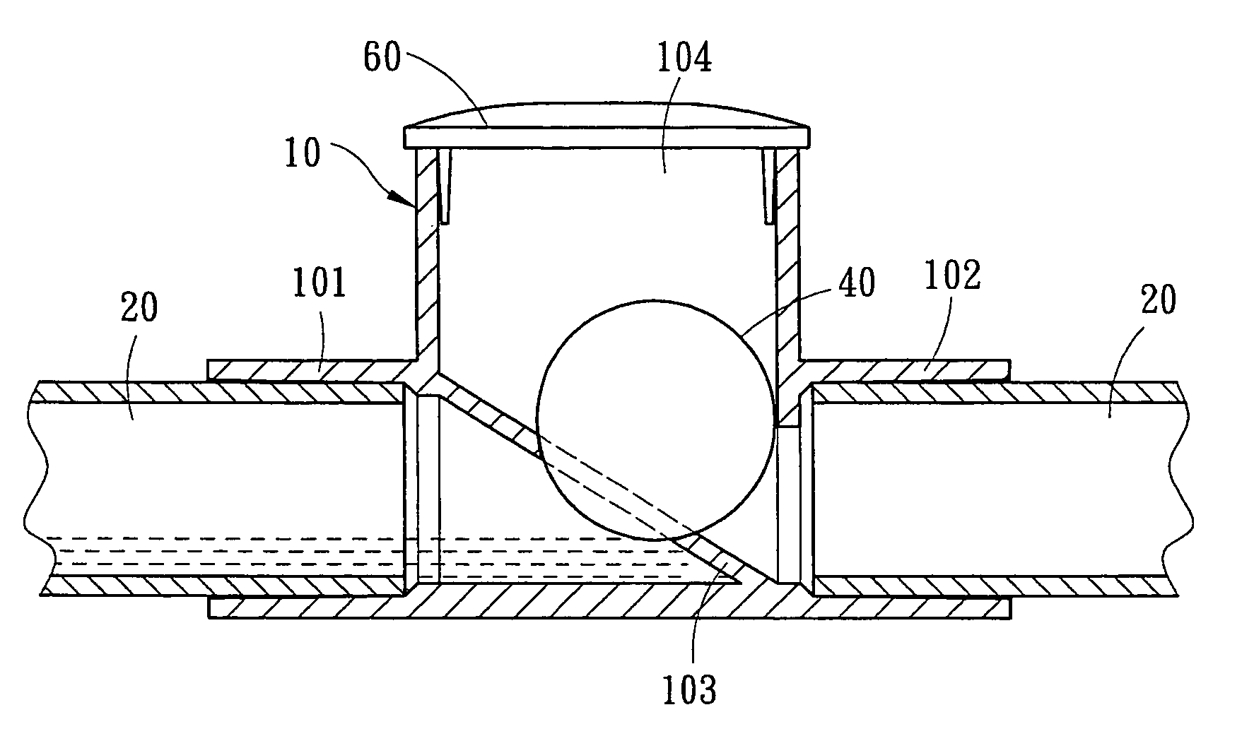
[0020]Please referring to FIGS. 3 and 4, the condensate drain trap for positive or negative pressure air handling unit according to the present invention includes a drain trap 10 connecting to a drain pipe 20 that are located on one side of an air handling unit 30 for drain the condensate water and preventing air from flowing into or out of the air handling unit 30.

[0021]The drain trap 10 has a water inlet 101 and a water outlet 102 on two sides to connect to the drain pipe 20 by adhesive bonding. The drain trap 10 further has a valve seat 103 located therein communicating with the water inlet 101 and the water outlet 102. On the valve seat 103 there is a retaining element 40 in contact with the valve seat 103 in normal conditions at a first position.

[0022]The drain trap 10 may be made from thermal setting material such as PVC, PE, PP or the like that have a desired allowance, or metal with a desired toughness such as copper or iron. The drain trap 10 is coupled with an extension of...


PUM


Abstract

A dual function condensate drain trap for positive or negative pressure air handling unit applicable in positive or negative pressure environments by switching connecting directions includes a drain trap which has a water inlet and a water outlet on two sides to connect to a drain pipe, and a valve seat and a retaining element located on the valve seat movable between a first position to be in contact with the valve seat and a second position to be away from the valve seat. When the pressure of water column in the water inlet is smaller than that of the water outlet, the retaining element is on the first position to form an air lock to prevent air from entering or escaping from air handling unit. By contrast, when the pressure of water column in the water inlet is greater than that of the water outlet, the retaining element is moved to the first position to drain water.

Description

FIELD OF THE INVENTION[0001]The present invention relates to a dual function condensate drain trap for negative or positive pressure air handling unit (or positive or negative pressure air ducts) and particularly to using a float ball as a drain trap to drain the water and form an air lock to prevent air entering or escaping from an air handling unit.BACKGROUND OF THE INVENTION[0002]These days a great number of high rise buildings have been constructed. They are mostly designed with a sealed space. Hence air conditioning system is very important for those buildings.[0003]An A / C system generally equipped with a negative pressure (draw through type) air handling unit or positive pressure (blow through type) air handling unit, the drain pan outlet should be on the downstream side of the coil. A conventional condensate drain trap.[0004]Please refer to FIG. 1, an air handling unit 1a which is mounted onto a foundation base 3a and coupled with a trap 2a on one side. The trap 2a generally ...

Claims


Application Information

Patent Timeline
Patent Type & Authority Patents(United States)
IPC IPC(8): F25D21/14F16T1/22F24F13/22
CPCF16T1/22F24F13/222
Inventor YANG, SAM
Owner YANG SAM
Why Eureka
Try Eureka