Method and apparatus for forming a threaded hole in a hydroformed part

a technology of hydroformed parts and threaded holes, which is applied in the direction of metal working apparatus, etc., can solve the problems of insufficient thickness of the hydroformed parts and the first hole formed in the part, so as to reduce the requirements of the tool actuator, reduce the possibility of the surrounding wall falling off, and improve the hole definition

Inactive Publication Date: 2005-08-23
GM GLOBAL TECH OPERATIONS LLC
View PDF19 Cites 33 Cited by
  • Summary
  • Abstract
  • Description
  • Claims
  • Application Information

AI Technical Summary

Benefits of technology

[0010]The thread-forming portion of the tool has a full thread that with the intervening relief portion is an interrupted continuation of the partial thread and has the same pitch but a relatively sharp edged crest and a larger major diameter. The full thread is by selection of the proper thread forming configuration adapted to form the required thread in the wall of the hole on continued tool advancement and now turning of the tool in the proper direction. Wherein the tool is fed at a feed rate equal to the pitch of the tool threads (both the full and the partial thread) and that of the required thread. And wherein the relief portion of the tool minimizes the friction for starting rotation of the tool to form the thread where after the trailing full thread of the tool at the above feed rate produces a strong and precise thread in the extruded annular section of the hydroformed part by displacing or reorienting material rather than removing material as with a thread cutting tap.
[0012]In the operational description above, the tool is not rotated during the piercing, extruding and hole-sizing operations to minimize the requirements of the tool actuator. On the other hand, the tool may also be rotated during these operations with the result that better hole definition is made possible by reducing the possibility of collapse of the surrounding wall of the part. Moreover, with the present invention the threaded hole can be formed concurrently with the formation of one or more holes that are also required in the hydroformed part using a hydropiercing operation. As a result, the formation of the threaded hole using both a hydropiercing operation and a hydrotapping operation in forming a required threaded hole in the part in accordance with the present invention and concurrently with a separate hole forming hydropiercing operation still does not add substantially to the total cycle time required to process a part that requires both a threaded hole and a plain hole. And with the added advantage that neither a slug or chips are produced in the processing of such a part.

Problems solved by technology

However, conventional thread forming taps while not producing chips nevertheless still require that a hole first be formed in the part.
Furthermore, the wall of the hydroformed parts is typically not thick enough to allow the number of threads necessary to securely hold a particular screw or bolt to the hydroformed part or to allow the use of self-tapping screws or bolts.

Method used


Image

  • Method and apparatus for forming a threaded hole in a hydroformed part
  • Method and apparatus for forming a threaded hole in a hydroformed part
  • Method and apparatus for forming a threaded hole in a hydroformed part

Examples


Embodiment Construction

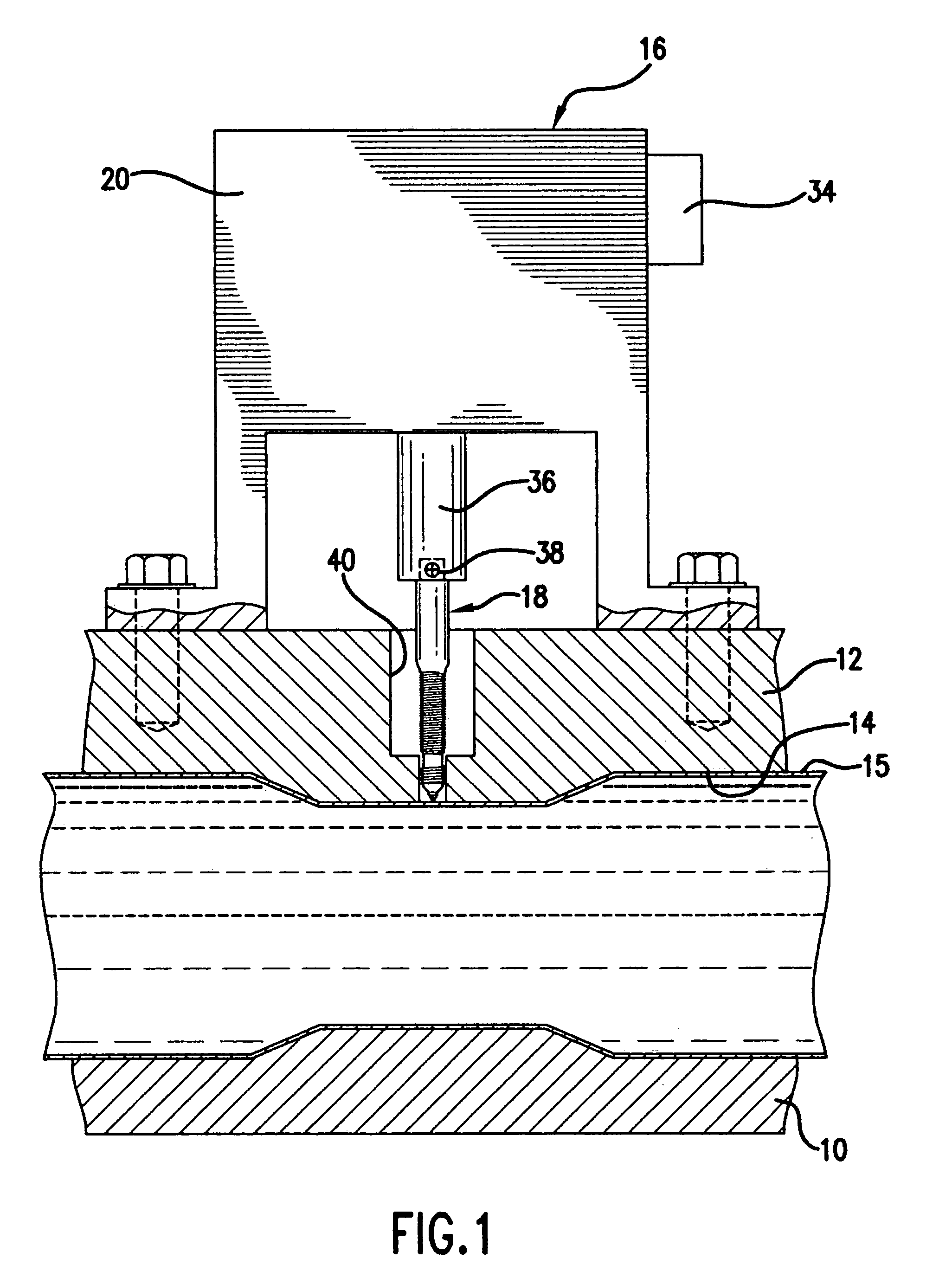
[0022]Referring to FIG. 1, there is shown a portion of a conventional hydroforming apparatus comprising a lower die 10 and an upper die 12 that co-operatively form a cavity 14 having a surface conforming to the required shape of the finished part. In the hydroforming process and in a conventional manner, a piece of tubular metal stock is captured between the dies in the die cavity and a hydroforming fluid typically in the form of a water based liquid solution is then delivered through one end of the part to the interior of the part while exit from the other end is blocked. With the hydroforming fluid thus delivered being maintained at a pressure sufficient to forcibly expand the wall of the captured part outward against and conform to the cavity surface to thereby form a hydroformed part 15 having the required shape. It will also be understood that following the formation of a threaded hole required in the hydroformed part as described below and also possibly the formation of one or...


PUM

PropertyMeasurementUnit
diameteraaaaaaaaaa
pressureaaaaaaaaaa
inner diameteraaaaaaaaaa

Abstract

Method and apparatus are disclosed wherein a required threaded hole is formed in a hydroformed part with a single tool while the part remains in a hydroforming die cavity. In forming the threaded hole, a hole is first pierced in the wall of the part and then an annular region of the part extending about the hole is extruded inwardly to form an integral tubular neck defining a hole of predetermined depth. The hole is then expanded in a sizing operation to a diameter determined by the required thread to be formed therein by material displacement and the required thread is then formed in the wall of the hole in a material displacing manner.

Description

TECHNICAL FIELD[0001]This invention relates to forming a threaded hole in a hydroformed part and more particularly to doing so while the part remains in the hydroforming dies.BACKGROUND OF THE INVENTION[0002]There is a desire in the production of hydroformed tubular metal parts to be able to form a precise and accurate threaded hole in the hydroformed part. Without requiring that this be done as a secondary operation following removal of the part from the hydroforming dies as is presently done. Recognizing that if a required threaded hole could be made in an in-die procedure while the hydroformed part remains in the dies and without producing a slug or chips, there are considerable time and cost savings to be gained.[0003]Moreover, it is known that required holes of various shapes can be pierced in the hydroformed part in a hydropiercing and extruding operation while the part remains in the dies under internal pressure and without producing a slug that could fall into the part and l...

Claims


Application Information

Patent Timeline
Patent Type & Authority Patents(United States)
IPC IPC(8): B21D28/28B21D28/24
CPCB21D28/28Y10T29/49805Y10T83/0596
Inventor GHIRAN, MIRCEA M.MELLAS, SPYROS PETEKAUFMAN, BENJAMIN D
Owner GM GLOBAL TECH OPERATIONS LLC
Why Eureka
Try Eureka