Quilting table for a sewing machine

a sewing machine and quilting technology, applied in the field of quilting equipment, can solve the problems of difficulty in hand stitching, and inability to move the fingers, and achieve the effects of facilitating the loading and alignment of fabrics, avoiding wheel derailment, and being easy to assembled

Inactive Publication Date: 2005-08-23
PFEIFER THOMAS A
View PDF9 Cites 15 Cited by
  • Summary
  • Abstract
  • Description
  • Claims
  • Application Information

AI Technical Summary

Benefits of technology

[0011]Accordingly, it is an advantage of the present invention that a quilting table for use with a sewing machine is provided.
[0012]It is another advantage of the present invention that the quilting table is provided in which wheel derailment is largely prevented.
[0013]Another advantage of the present invention is that a quilting table is provided that has user selectable fabric tensioning capability.
[0014]Another advantage of the present invention is that a quilting table is provided with concurrent visibility of both a quilting guide and the fabric.
[0015]Yet another advantage of the present invention is that a quilting table is provided that is readily assembled, and facilitates the loading and alignment of fabric onto the quilting table.
[0016]The above and other advantages of the present invention are carried out in one form by a quilting table for use with a sewing machine. The quilting table includes a frame having first and second side rails. The first and second side rails support a front box channel rail in opposing relationship with a rear box channel rail. The front and rear rails define a longitudinal dimension of the frame, and the first and second side rails define a transverse dimension of the frame. A first carriage has first grooved wheels engaged with first and second facing edges of the front and rear box channel rails, the first carriage being moveable relative to the longitudinal dimension. A second carriage supports the sewing machine. The second carriage has second wheels engaged with opposing rails of the first carriage and is moveable relative to the transverse dimension.

Problems solved by technology

Complex designs and patterns are often hand-stitched by a skilled craftsperson due to the complications involved with attempting to manipulate an unwieldy, multilayered fabric sandwich under the needle bar of a conventional sewing machine.
However, such hand-stitching can be too time consuming for a skilled craftsperson, and may be too challenging for those who are not as skilled at hand-stitching.
In addition, hand-stitching may be difficult or even impossible for those with limited mobility of their fingers, such as for an individual who has arthritis.
Unfortunately, long arm sewing machines can be complex, bulky, and undesirably costly for the average hobbyist.
Furthermore, if a hobbyist already has a conventional, household sewing machine, the additional long arm sewing machine presents commensurate storage related problems.
By merely utilizing a long arm machine or a household sewing machine, the hobbyist must still manipulate the quilt relative to the machine which can be difficult, and cause puckering and stitching errors.
Several problems exist with these prior art quilting devices.
Unfortunately, wheels setting upon a track have a tendency to become derailed, which can be inconvenient and / or lead to equipment damage.
These track sections can disassemble in operation also leading to derailment of the wheels.
Unfortunately, the use of a gear and pawl provides stepwise tensioning.
Consequently, a user may have to decide whether the fabric should be tensioned too much or less than a desired amount of fabric tensioning.
Inappropriate tensioning of the fabric can lead to puckering or loose stitches, which is obviously undesirable to the look of the finished product.
Unfortunately, a rear driven machine and stylus located near the rear of the machine results in poor visibility of the fabric under the needle bar.
As such, it is difficult for the user to visualize both the traced pattern and the sewn fabric concurrently to verify the accuracy of the stitching.
Still other problems exist with prior quilting devices in terms of complexity of setup, bulky size, difficulty of fabric loading onto the rollers, and so forth.

Method used


Image

  • Quilting table for a sewing machine
  • Quilting table for a sewing machine
  • Quilting table for a sewing machine

Examples


Embodiment Construction

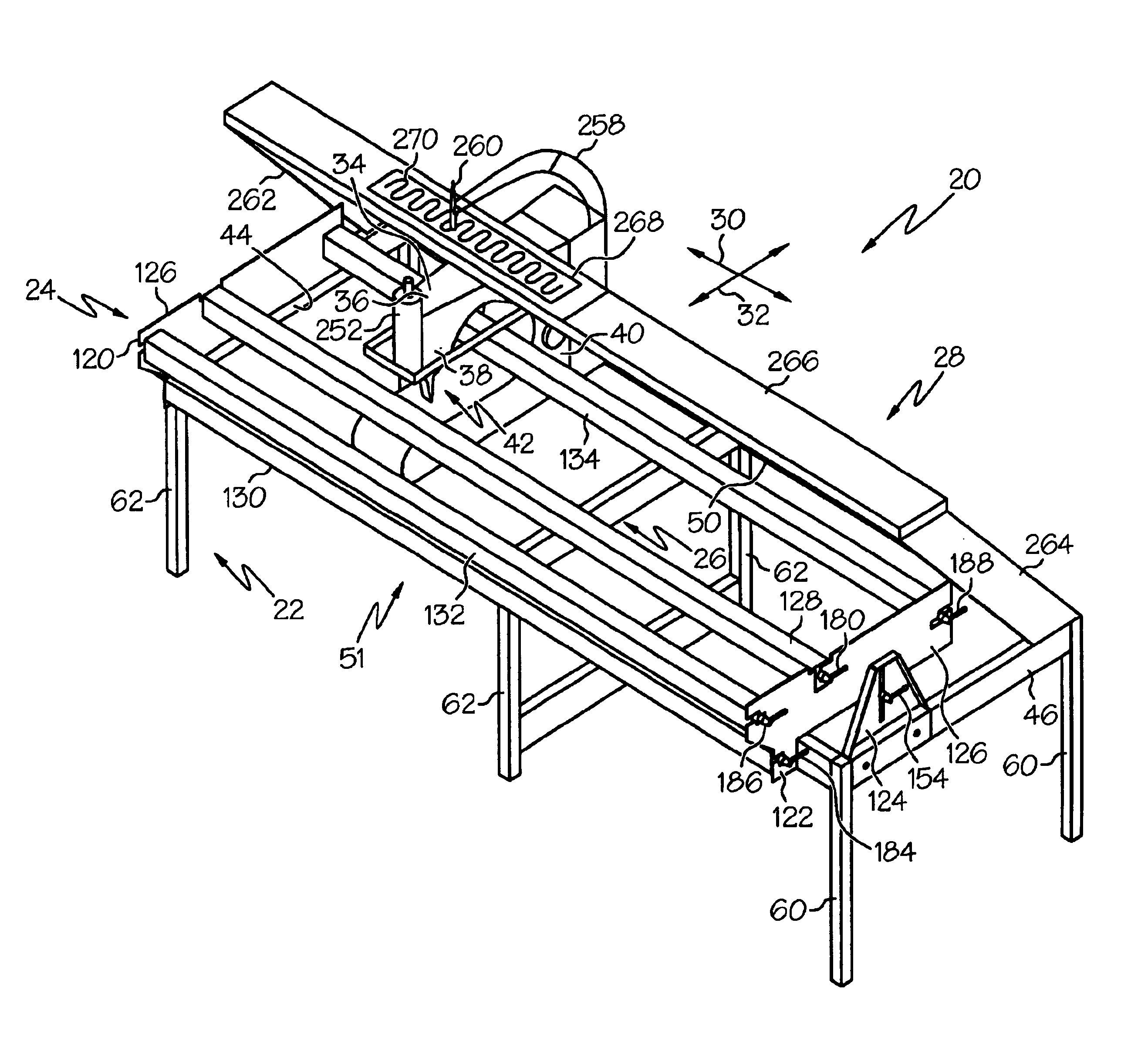
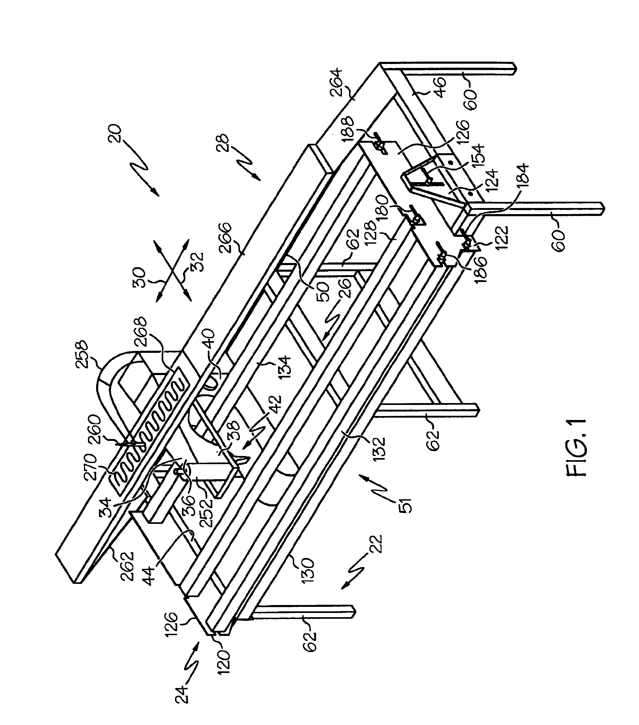
[0036]FIG. 1 shows a front perspective view of a quilting table 20 in accordance with a preferred embodiment of the present invention. Quilting table 20 generally includes a frame 22, a fabric support system 24, a platform assembly 26, and an overhead shelf 28. Platform assembly 26 is moveable relative to a longitudinal dimension 30 and a transverse dimension 32 of frame 22. In a preferred embodiment, platform assembly 26 supports and transports a conventional, household sewing machine 34 having a machine head 36 on the end of an arm 38 extending from a base structure 40. The open region beneath arm 38 and between each of machine head 36 and base structure 40 is commonly referred to as a throat 42.

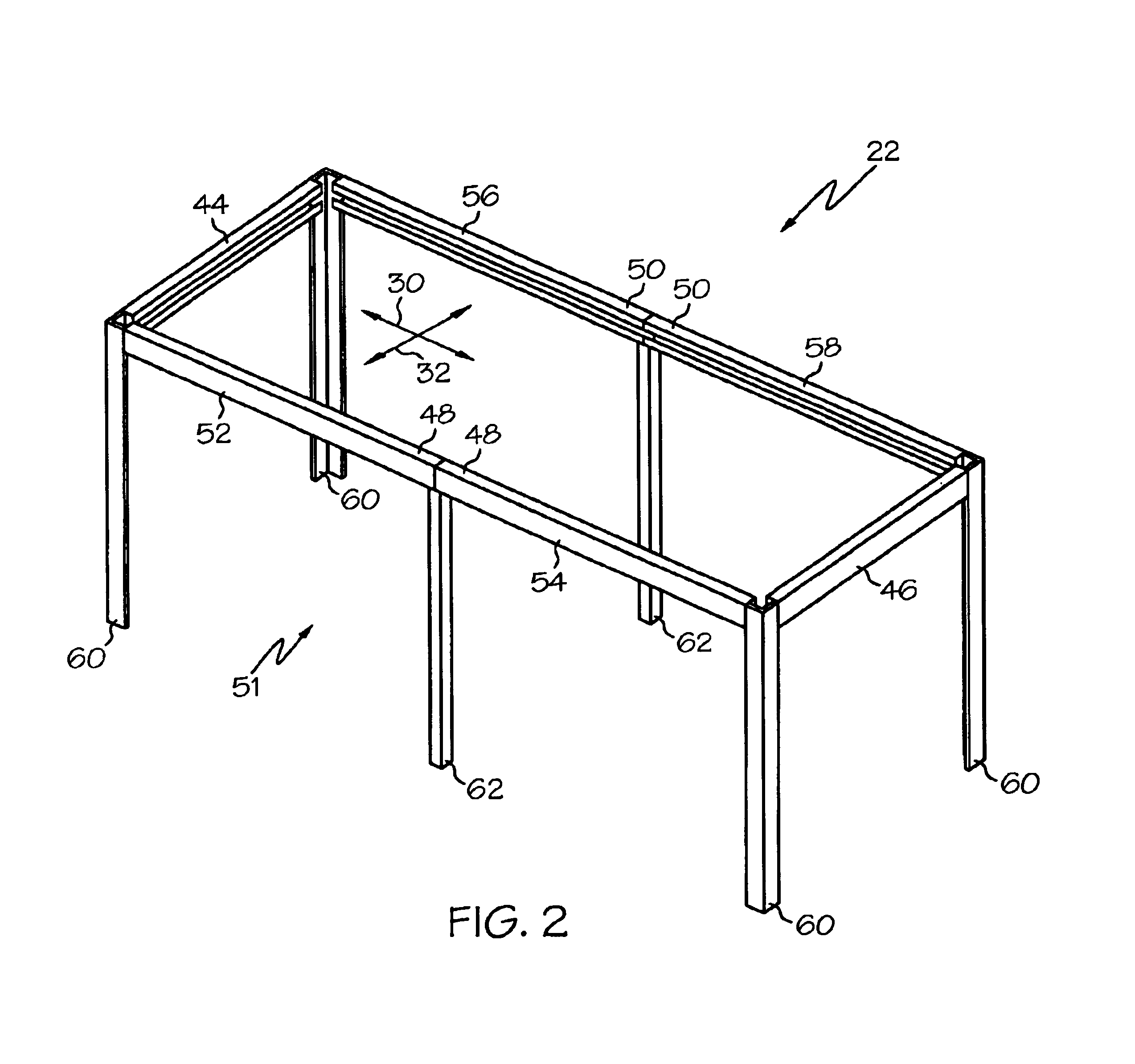
[0037]Referring to FIG. 2 in connection with FIG. 1, FIG. 2 shows front perspective view of frame 22. Frame 22 includes a first side rail 44 and a second side rail 46 supporting a front box channel rail 48 and a rear box channel rail 50. Front and rear box channel rails 48 and 50, respecti...


PUM


Abstract

A quilting table (20) includes a frame (22) having box channel rails (50, 52), a first carriage (212), moveable relative to a longitudinal dimension (30) of the frame (22), having wheels (224) engaged with the box channel rails (50, 52), and a second carriage (214), moveable relative to a transverse dimension (32) of the frame (22), supporting a sewing machine (34). A fabric support system (24) includes three fabric payout bars (128, 130, 132) and a take-up bar (134). Compressive force is utilized between the bars (128, 130, 132, 134) and their supports (120, 122) for fabric tensioning. The bars have a rectangular cross-sectional shape and indicia (190) for facilitating fabric placement. An overhead shelf (28) extends across dimension (30) of the frame (22) so that an operator on a needle side (51) of the quilting table (20) can currently view a quilting guide (268) and the fabric (206).

Description

RELATED INVENTION[0001]The present invention claims priority under 35 U.S.C. §119(e) to: “MACHINE QUILTING TABLE,” U.S. Provisional Patent Application Ser. No. 60 / 455,475, filed 17 Mar. 2003, which is incorporated by reference herein.TECHNICAL FIELD OF THE INVENTION[0002]The present invention relates to the field of quilting equipment. More specifically, the present invention relates to quilting tables for use with conventional sewing machines.BACKGROUND OF THE INVENTION[0003]Quilting has been in practice for many years, initially for utilitarian purposes, and more recently as a way of artistic expression. The continued popularity of the craft has lead to the development of modern textiles, equipment, and labor-saving sewing devices.[0004]Quilting typically entails sewing two layers of cloth with a layer of insulating batting in between, thus forming a quilt. Quilts may be formed in a variety of shapes and styles that are variously used to cover beds, to decorate walls, used as lap ...

Claims


Application Information

Patent Timeline
Patent Type & Authority Patents(United States)
IPC IPC(8): D05B39/00D05B11/00
CPCD05B11/00D05B39/005
Inventor PFEIFER, THOMAS A.
Owner PFEIFER THOMAS A
Why Eureka
Try Eureka