Vehicle heating and cooling system

a technology for heating and cooling systems and vehicles, applied in the direction of lighting and heating apparatus, operation modes of machines, instruments, etc., can solve the problems of consuming a considerable amount of power, consuming considerable fuel while the driver is resting, and heating by 110 volt air conditioner units

Inactive Publication Date: 2005-08-23
LONGHORN SCSF LTD
View PDF20 Cites 99 Cited by
  • Summary
  • Abstract
  • Description
  • Claims
  • Application Information

AI Technical Summary

Problems solved by technology

While idling, the main engine generates far more power than needed for heating and cooling, consequently consumes considerable fuel while the driver is resting.
Heating by a 110 volt air conditioner unit, however, consumes a considerable amount of power.
Many rest stops, however, do not have such provisions for connecting a vehicle to electrical power.

Method used


Image

  • Vehicle heating and cooling system
  • Vehicle heating and cooling system
  • Vehicle heating and cooling system

Examples


Embodiment Construction

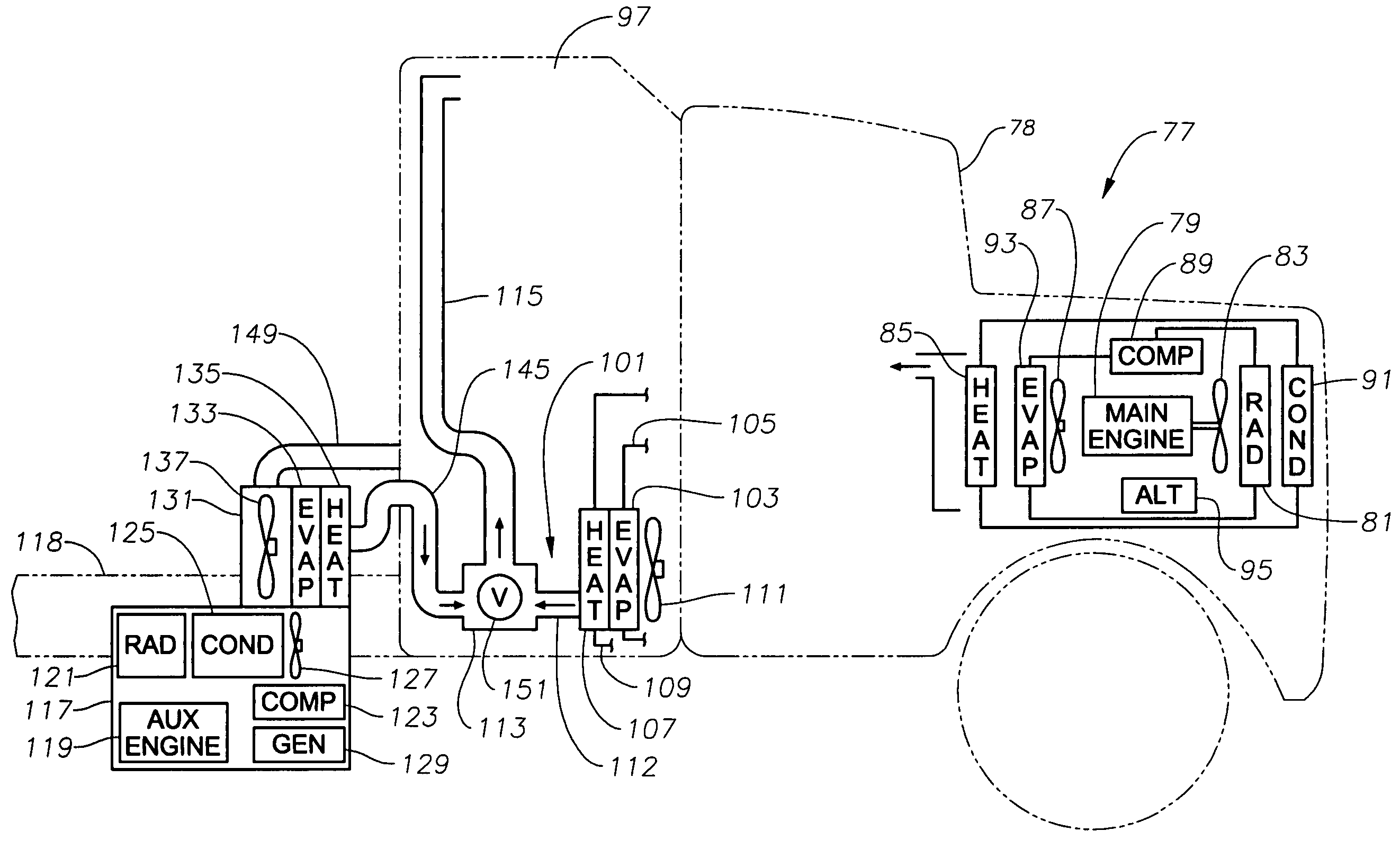
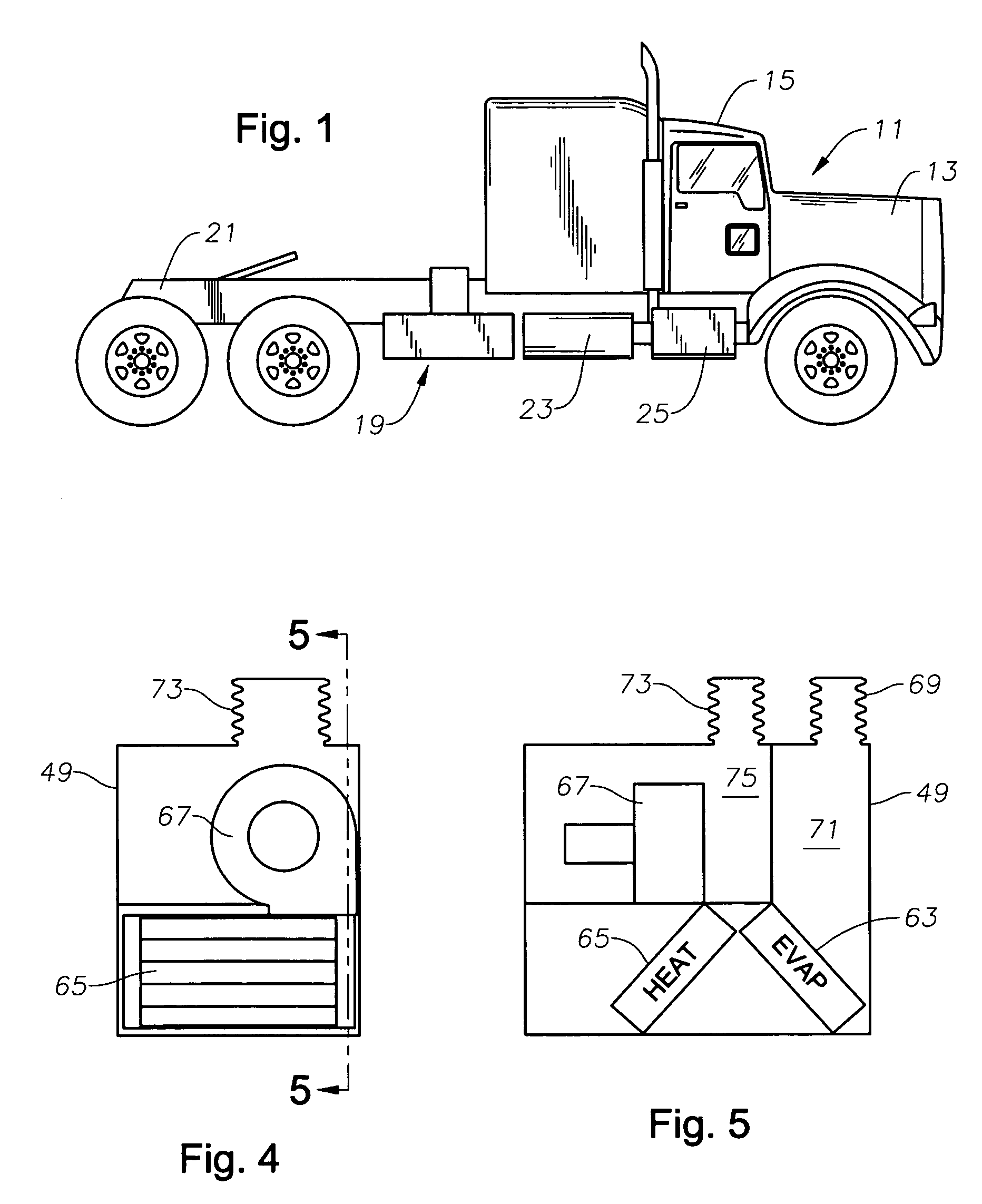
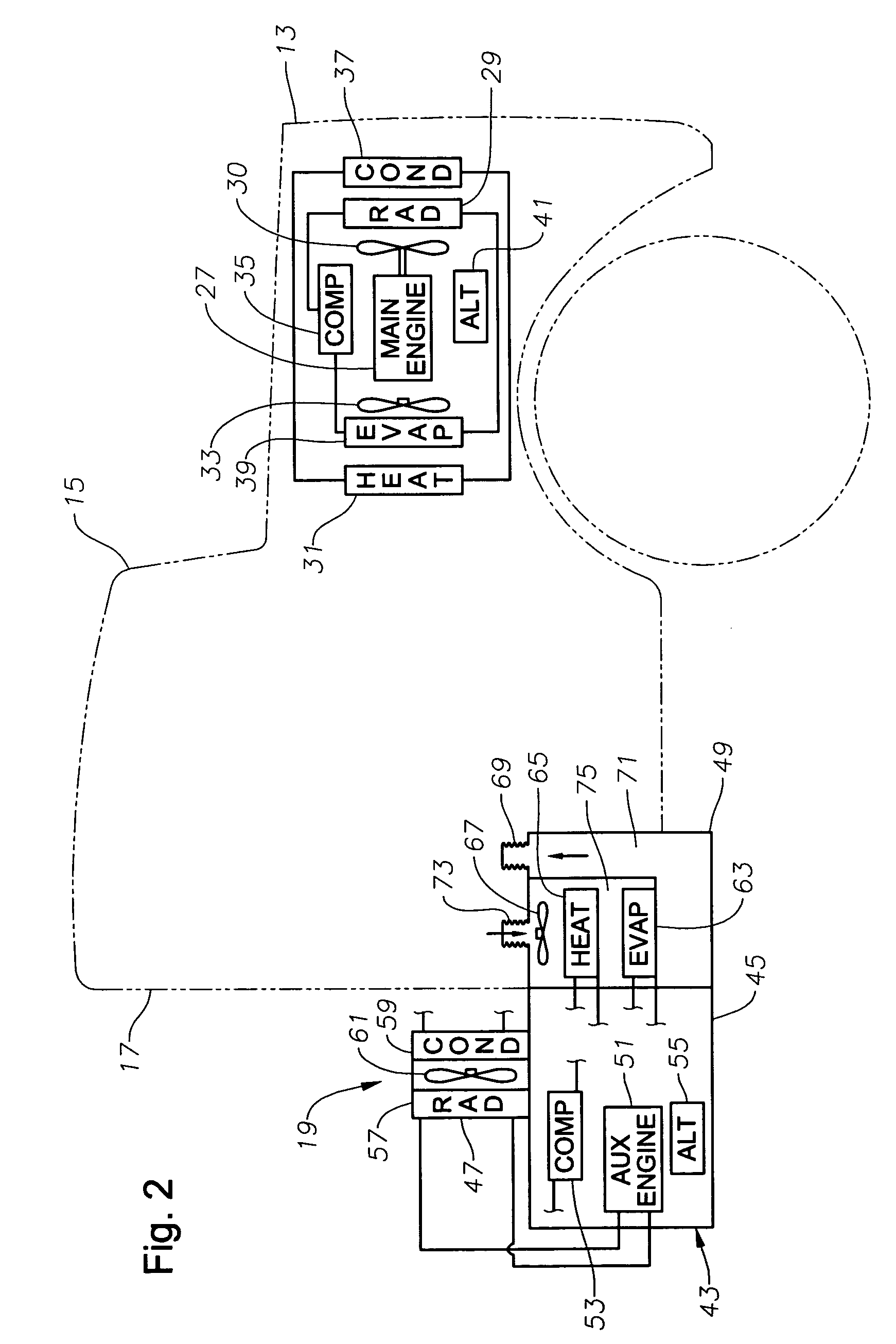
[0022]Referring to FIG. 1, truck 11 has an engine compartment 13 and a cab 15. Optionally, truck 11 may have a sleeper compartment 17 as shown in FIG. 2. The interior of sleeper compartment 17 is in common with the interior of cab 15.

[0023]An auxiliary air conditioning unit 19 is shown mounted to frame 21 of truck 11. Air-conditioning unit 19 is located at the rear of and below sleeper compartment 17 in this embodiment. In this embodiment, auxiliary air-conditioning unit 19 is located rearward of a fuel tank 23. Typically, truck 11 will also have a step box 25 located directly below cab 15 in front of fuel tank 23 for providing access to the interior of cab 15.

[0024]As shown in FIG. 2, truck 11 has a main or primary engine 27, normally a diesel, which propels truck 11. A main radiator 29 is connected by hoses to main engine 27 for receiving engine coolant. An engine fan 30 is directly driven by main engine 27 for causing air to flow through main radiator 29. Truck 11 also has a main...


PUM


Abstract

A heating and air-conditioning system has an auxiliary engine for heating and cooling of a vehicle while the primary engine of the vehicle is not operating. The vehicle has a sleeper compartment with a sleeper compartment air conditioning unit powered by the main engine. An auxiliary air conditioning system located exterior of the sleeper compartment is powered by the auxiliary engine. An auxiliary supply duct extends into the sleeper compartment and joins the duct of the sleeper compartment air conditioning unit. A valve operated by air pressure blocks air flow from the sleeper compartment air conditioning unit into the auxiliary duct while in the main position. In the auxiliary position, the valve blocks air flow from the auxiliary duct into the sleeper compartment air conditioning unit.

Description

CROSS-REFERENCE TO RELATED APPLICATION[0001]This invention is a continuation-in-part to Ser. No. 10 / 680,309, filed Oct. 7, 2003, now abandoned which claims priority to provisional application Ser. No. 60 / 416,633, filed Oct. 7, 2002.FIELD OF THE INVENTION[0002]This invention relates in general to heating and cooling systems for vehicles, and in particular to a system utilizing an auxiliary engine.BACKGROUND OF THE INVENTION[0003]Large tractor trucks typically have air-conditioning systems similar to automobiles. The truck engine drives a compressor that compresses refrigerant and delivers it to a condenser. The condenser converts the hot gaseous refrigerant to a liquid refrigerant. The refrigerant flows to an evaporator where it undergoes a pressure drop, converting the refrigerant to a cold gas. An interior fan flows air through the evaporator into the interior of the vehicle. The condenser is cooled by the main engine fan, which also flows air through the engine radiator.[0004]For ...

Claims


Application Information

Patent Timeline
Patent Type & Authority Patents(United States)
IPC IPC(8): G06Q20/00G07F7/08B60H1/00B60H1/32F25B27/00
CPCB60H1/00378B60H1/3226F25B27/00F25B2327/001F25B2400/06
Inventor BRUMMETT, KEIVPANNELL, BOBBY L.SHIELDS, NEAL G.TIGNER, ROBERT H.
Owner LONGHORN SCSF LTD
Why Eureka
Try Eureka