Method for making a well for removing fluid from a desired subterranean formation

a technology of subterranean formation and well, which is applied in the direction of well accessories, boreholes/wells, foundation engineering, etc., can solve the problems of inefficiency of horizontal well for removing desired fluid, inefficiency of vertical well, and inability to drain large amount of desired fluid around, so as to facilitate the removal of cuttings

Inactive Publication Date: 2005-08-23
CNX GAS +1
View PDF41 Cites 27 Cited by
  • Summary
  • Abstract
  • Description
  • Claims
  • Application Information

AI Technical Summary

Benefits of technology

[0014]This invention also provides for a method for removing fluid from a desired subterranean formation having a main directional well bore that extends from a top surface at ground level into the desired subterranean formation. An intermediate casing having an attached external parasite tube that extends from the top surface to a point of intersection with the intermediate casing. Air pressure can be inserted down the parasite tube. Drilling fluid can be inserted down a drill string within the intermediate casing to create hydrostatic pressure less than a desired subterranean zone breakdown pressure which provides an underbalanced drilling environment and facilitates the removal of cuttings and drilling fluid to be circulated to the top surface at ground level through the intermediate casing. An interface zone that is coupled to the main directional well bore is drilled using the underbalanced drilling environment. A lateral well bore that is coupled to the interface zone is drilled using the underbalanced drilling environment. A directional sump bore that is coupled to the interface zone is drilled using the underbalanced drilling environment. The directional sump bore extends from the interface zone to a point below the interface zone. A means for moving fluid from the directional sump bore is used to move fluid from the directional sump bore through the main directional well bore to the top surface.

Problems solved by technology

In prior art methods that only use a horizontal well having only a substantially vertical section, curved section and a horizontal section it is difficult to remove the other fluid and thus makes the horizontal well inefficient for removing the desired fluid.
However, vertical wells only drain a small amount of desired fluid around the radius of the vertical well because it only intersects a few natural fractures within the subterranean formation without any external stimulation.
Thus the vertical well can be inefficient for removing desirable fluid from the subterranean formation.
However this method requires two wells that can be inefficient and expensive.
In addition it is difficult and costly to intersect a vertical well and a horizontal well.
This method may require a cavity to be excavated at the bottom of the vertical well that can add additional cost.

Method used


Image

  • Method for making a well for removing fluid from a desired subterranean formation
  • Method for making a well for removing fluid from a desired subterranean formation
  • Method for making a well for removing fluid from a desired subterranean formation

Examples


Embodiment Construction

Definitions

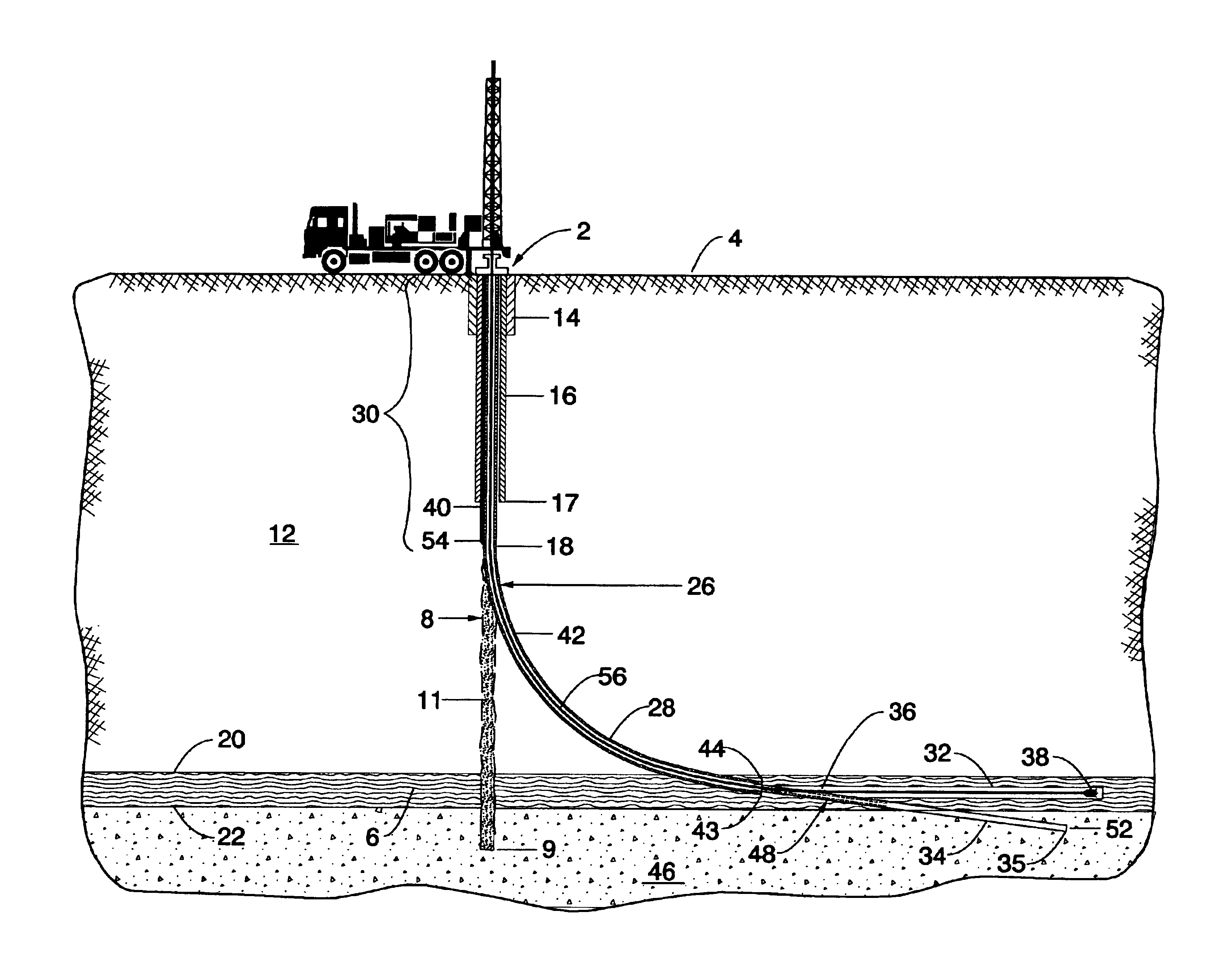
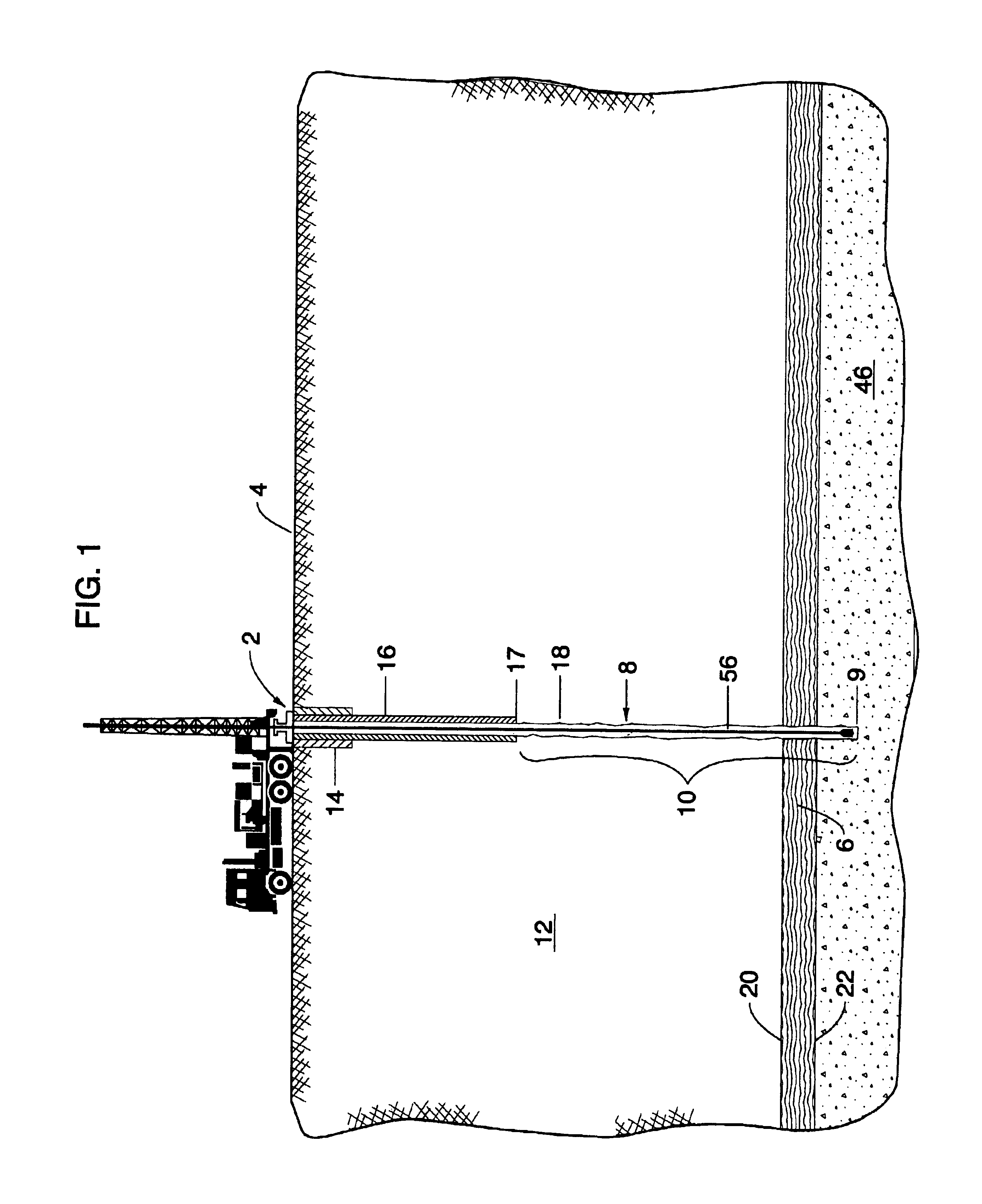
[0027]“Well” means an orifice in the ground made by drilling, boring or any other means, from which fluids such as water, oil and gas are recovered or that was made for the purpose of recovering such fluids. A well may also provide a means for injecting fluids into a subterranean formation. A well is drilled from a surface elevation to a desired subterranean formation(s) providing a conduit for injecting fluids and / or removing fluids from the formation(s).

[0028]“Fluid” means all liquids and gases including but not limited to water, brine, chemically entrained liquids, foam, air, nitrogen or hydrocarbons injected into and / or removed from a well.

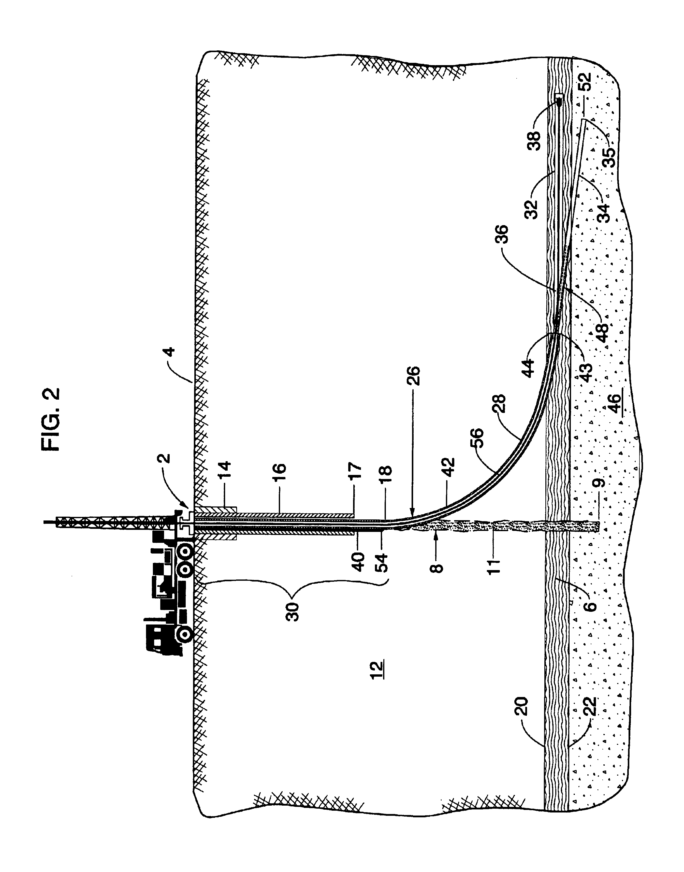
[0029]“Interface Zone” means a zone within a desired subterranean formation where: a) a main directional well bore, b) a lateral well bore and c) a directional sump bore all interconnect.

[0030]“Main Directional Well Bore” means a well bore comprised of a substantially vertical section and a substantially curved section drilled from ...


PUM


Abstract

An improved method for making a well for removing fluid from a desired subterranean formation. This invention provides for a method for making a well for removing fluid from a desired subterranean formation having an interface zone. The interface zone is coupled to a main directional well bore that extends from a top surface at ground level into the desired subterranean formation. A lateral well bore is also coupled to the interface zone. A directional sump bore is also coupled to the interface zone and the directional sump bore extends from the interface zone to a point below the interface zone. There is also a means for moving fluid from the directional sump bore through the main directional well bore to the top surface.

Description

BACKGROUND OF THE INVENTION[0001]1. Field of the Invention[0002]This invention relates generally to removing fluid from a subterranean formation and more particularly to a method for making a well for removing fluid from a desired subterranean formation.[0003]2. Background of the Invention[0004]Subterranean formations often contain desirable fluids that can be used for many applications. Therefore there is need to remove the desirable fluids from the subterranean formation. The subterranean formations often extend horizontally over many thousands of feet and are often very shallow in depth.[0005]One prior art method used to remove desired fluids from a subterranean formation is drilling a horizontal well. The horizontal portion of the well may extend over a significant length of the subterranean formation. When the horizontal portion of the well extends over a significant length of the subterranean formation it intersects multiple natural fractures within the subterranean formation....

Claims


Application Information

Patent Timeline
Patent Type & Authority Patents(United States)
IPC IPC(8): E21B43/00E21B43/30E21B41/00E21B21/00
CPCE21B41/0035E21B43/305E21B2021/006E21B21/085
Inventor MORGAN, CLAUDEFANNING, GEOFF W.AMAN, JOSEPH P.VARCOE, BRIANKOLKMEIER, ROBERTSTAYTON, ROBERTTOOTHMAN, RICHARD L.
Owner CNX GAS
Why Eureka
Try Eureka