
Nailer having positioning effect

a positioning effect and nailer technology, applied in the field of nailers, can solve the problems of reducing the lifetime of the locking plate, limiting the versatility of the conventional nailer, and reducing the positioning effect, so as to achieve the effect of efficiently positioning the washer, preventing the fatigue and enhancing the lifetime of the locking ring

Inactive Publication Date: 2005-08-23
YONG SONG HARDWARE & TOOL
View PDF8 Cites 16 Cited by
  • Summary
  • Abstract
  • Description
  • Claims
  • Application Information

AI Technical Summary

Benefits of technology

[0017]The primary objective of the present invention is to provide a nailer having a positioning effect to position a washer efficiently.
[0018]Another objective of the present invention is to provide a nailer, wherein the washer is positioned between the catch flange of the feed plate and the locking ring rigidly and stably, thereby facilitating a user combining the washer with the nail.
[0019]A further objective of the present invention is to provide a nailer, wherein the locking ring is tensioned only when the washer passes through the locking ring, so that the locking ring is not maintained at the tightened state constantly, thereby preventing the locking ring from producing fatigue, and thereby enhancing the lifetime of the locking ring.
[0020]A further objective of the present invention is to provide a nailer, wherein the locking ring is used to stop washers made of plastic or metallic material, thereby enhancing the versatility of the nailer.

Problems solved by technology

However, the locking plate 23 easily produces elastic fatigue during a long-term utilization, thereby decreasing the positioning effect of the locking plate 23, and thereby decreasing the lifetime of the locking plate 23.
However, the washer 1A is deformed by its flexibility so as to pass through the through hole 331 of the catch plate 33, so that such a conventional nailer is only available for washers made of plastic material and is not available for washers made of metallic material, thereby limiting the versatility of the conventional nailer.

Method used


Image

  • Nailer having positioning effect
  • Nailer having positioning effect
  • Nailer having positioning effect

Examples


Embodiment Construction

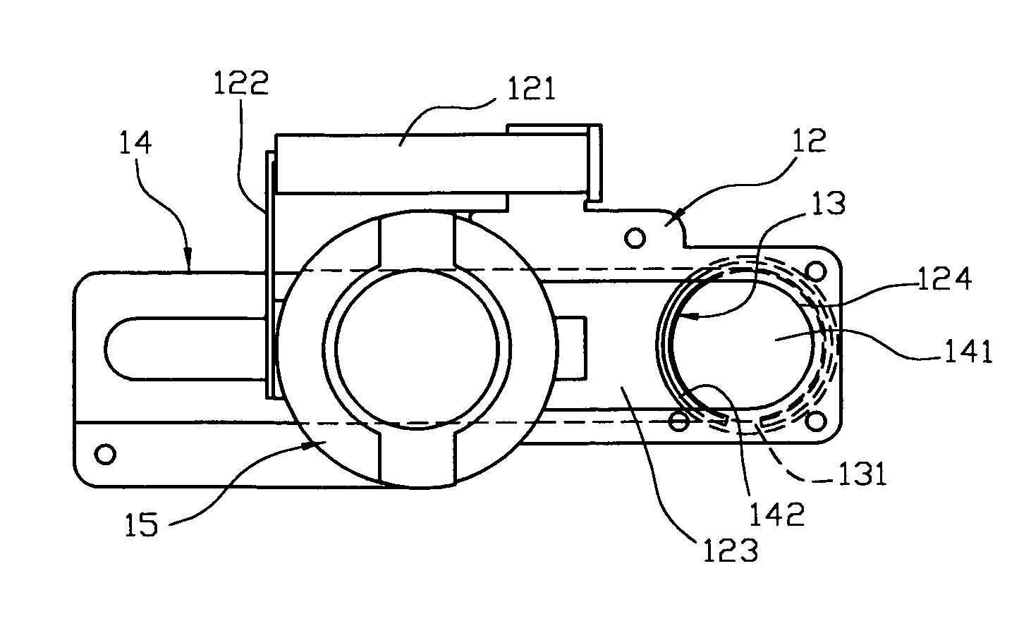
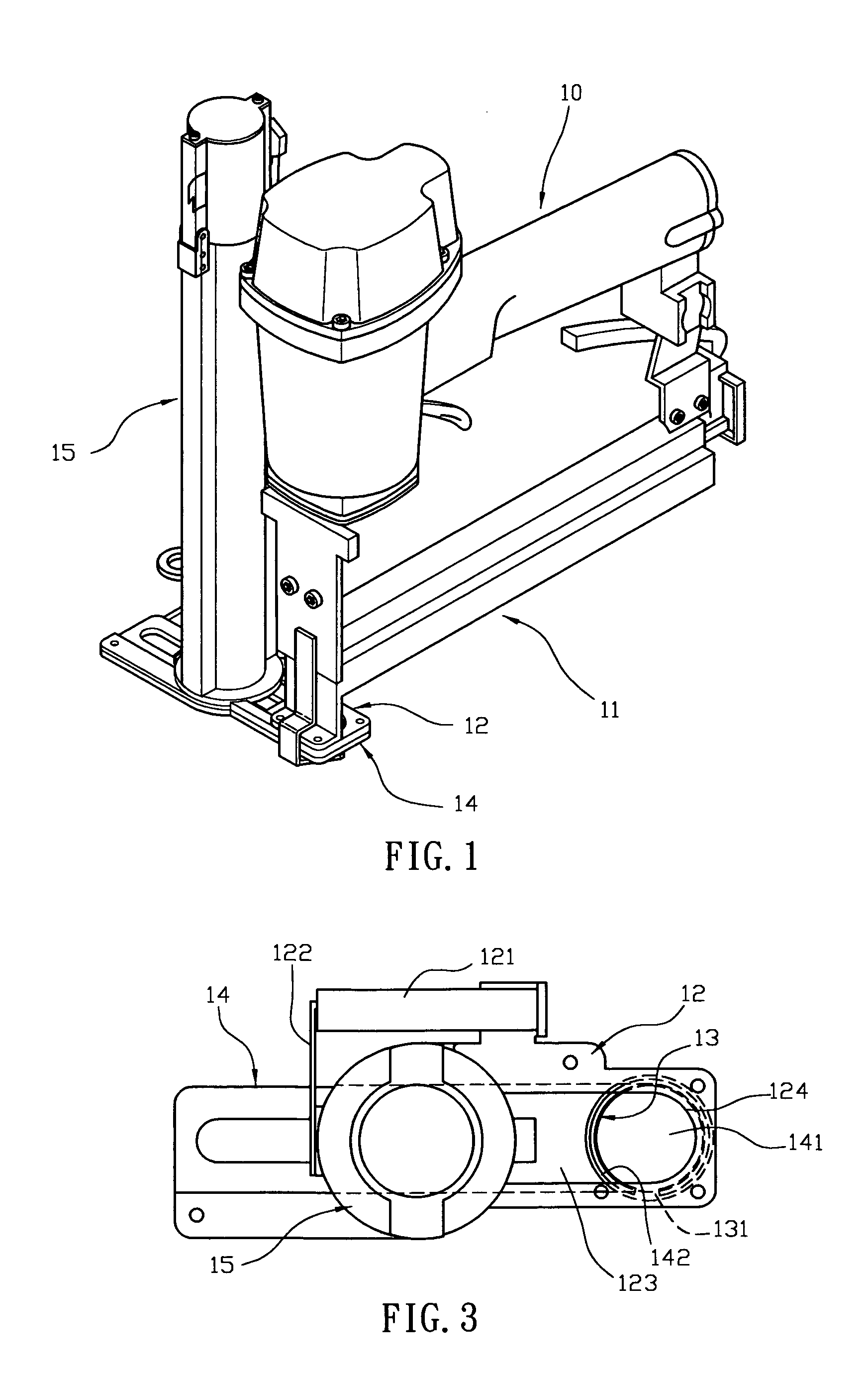
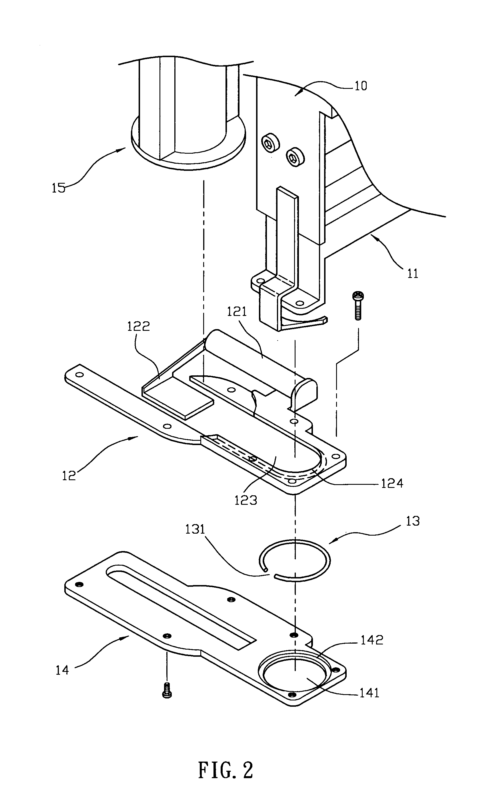
[0031]Referring to the drawings and initially to FIGS. 1–4, a nailer in accordance with the preferred embodiment of the present invention comprises a gun body 10, a magazine 11, a feed plate 12, a washer barrel 15, a catch plate 14, and a locking ring 13.

[0032]The magazine 11 is mounted on the gun body 10 and contains a plurality of nails (not shown) therein. The nails in the magazine 11 are ejected outward by the gun body 10.

[0033]The feed plate 12 is mounted on the gun body 10 and connected to the magazine 11. The feed plate 12 has a periphery provided with a propeller 121 having an end provided with a push bar 122. The feed plate 12 has an inside formed with an elongated slideway 123 having a periphery formed with an inward extended catch flange 124. Preferably, the slideway 123 is extended from a first end to a second end of the feed plate 12.

[0034]The washer barrel 15 containing a plurality of washers 100 (see FIG. 4) therein is mounted on the gun body 10 and connected to the m...


PUM


Abstract

A nailer includes a gun body, a magazine, a feed plate, a washer barrel, a catch plate, and a locking ring. Thus, the washer is closely positioned between the catch flange of the feed plate and the locking ring, thereby facilitating a user combining the washer with the nail. In addition, the locking ring is tensioned only when the washer passes through the locking ring, so that the locking ring is not maintained at the tightened state constantly, thereby preventing the locking ring from producing fatigue, and thereby enhancing the lifetime of the locking ring. Further, the locking ring is used to stop washers made of plastic or metallic material, thereby enhancing the versatility of the nailer.

Description

BACKGROUND OF THE INVENTION[0001]1. Field of the Invention[0002]The present invention relates to a nailer, and more particularly to a nailer having a positioning effect to position a washer efficiently.[0003]2. Description of the Related Art[0004]A conventional nailer in accordance with the prior art shown in FIGS. 6–8 comprises a gun body 20, a magazine 21 mounted on the gun body 20 and containing a plurality of nails (not shown) which are ejected outward by the gun body 20, a feed plate 22 mounted on the gun body 20 and having a first end provided with a propeller 221 having an end provided with a push bar 222 and a second end formed with a through hole 223, a washer barrel 26 mounted on the gun body 20 and containing therein a plurality of washers 1 (see FIG. 8) made of plastic or metallic material, a catch plate 25 mounted on the feed plate 22 and having a top formed with an elongated slideway 251 having an end formed with a through bore 252 facing the through hole 223 of the fe...

Claims


Application Information

Patent Timeline
IPC IPC(8): B25C5/00B25C5/16
CPCB25C5/1693
Inventor CHOU, CHIEN-CHI
Owner YONG SONG HARDWARE & TOOL
Learn More