
Seated stepper

a stepper and stepper technology, applied in the field of steppers, can solve the problems of non-uniform or variable resistance of steppers, potential injury to exercisers, and difficulty in maintaining proper resistance in steppers, and achieve the effect of reducing the intensity of exercis

Inactive Publication Date: 2005-08-23
NORTHLAND INDS
View PDF8 Cites 78 Cited by
  • Summary
  • Abstract
  • Description
  • Claims
  • Application Information

AI Technical Summary

Benefits of technology

[0005]It is a general object of the present invention to provide an exercise machine which uses an alternating linear stepping or leg pressing motion to provide a lower body workout.
[0006]It is one object of the present invention to provide a leg exercise machine that combines the comfort and support of a seated exercise position with a striding type of motion which will improve muscular and aerobic conditioning.

Problems solved by technology

Some steppers provide non-uniform or variable resistance because of the use of chains, cables and springs which do not provide solid linkages.
The variable or jerking motions that sometimes occur can cause potential injury to exercisers.
The maintaining of proper resistance in steppers is also a problem because of the arcuate or curved path of their exercise movements which can vary the mechanical lever created between the exerciser and the stepper.
However, the use of a rack and pinion can create frictional forces that undesirably reduce the efficiency of the steppers and can cause significant wear of some stepper components.
A further drawback is the large number and complex arrangement of parts which leads to higher costs of production and possible future maintenance requirements.

Method used


Image

  • Seated stepper
  • Seated stepper
  • Seated stepper

Examples


Embodiment Construction

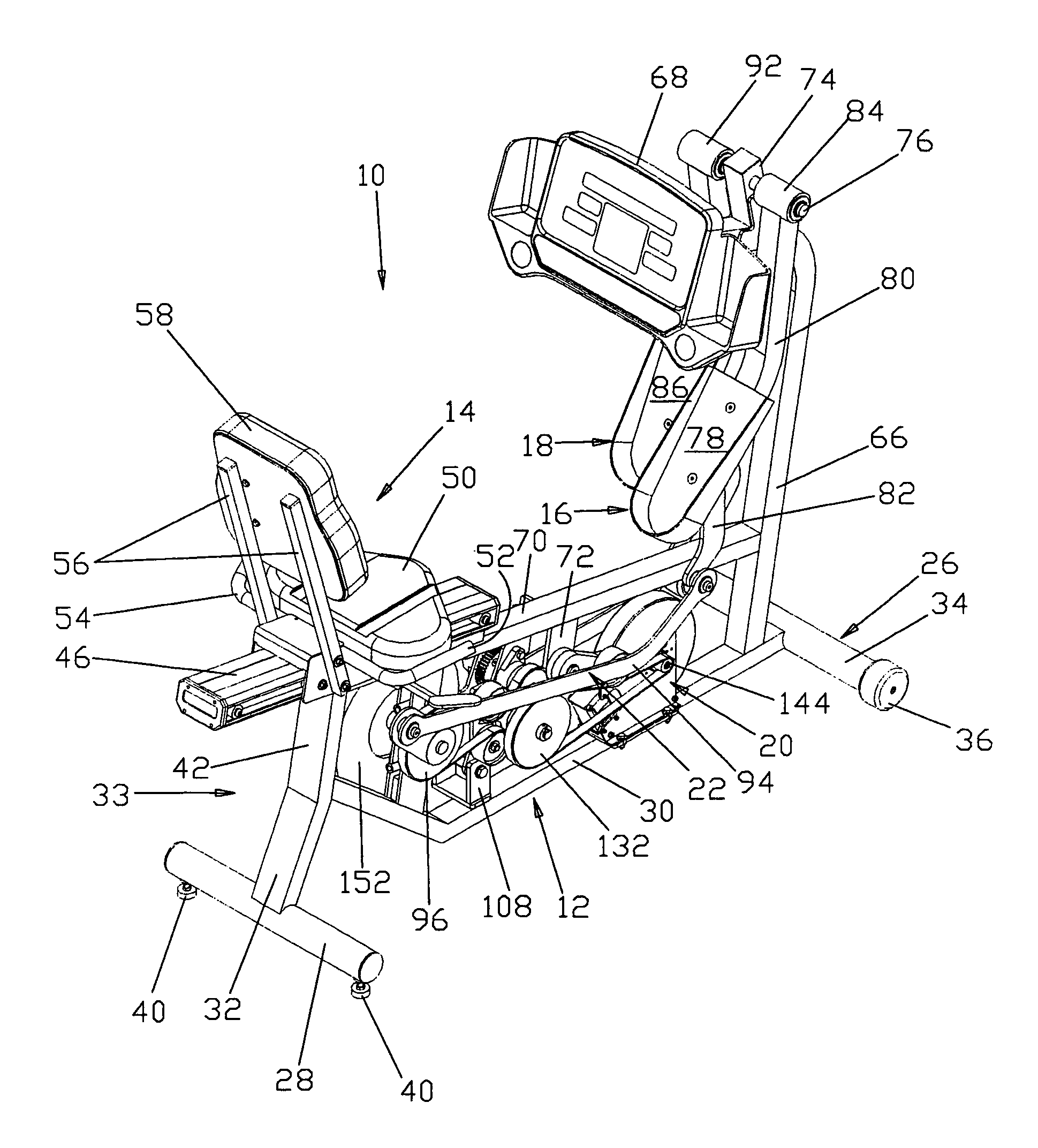
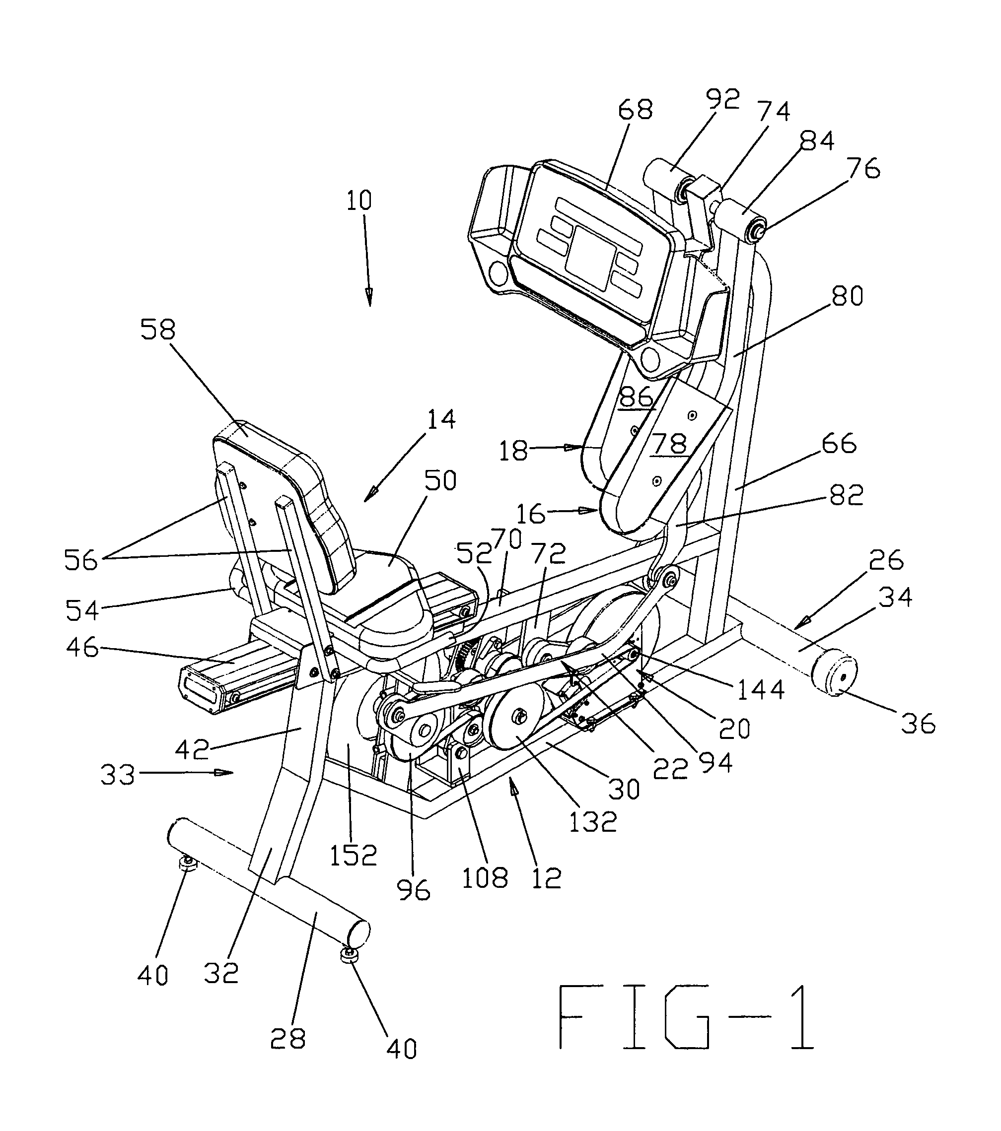
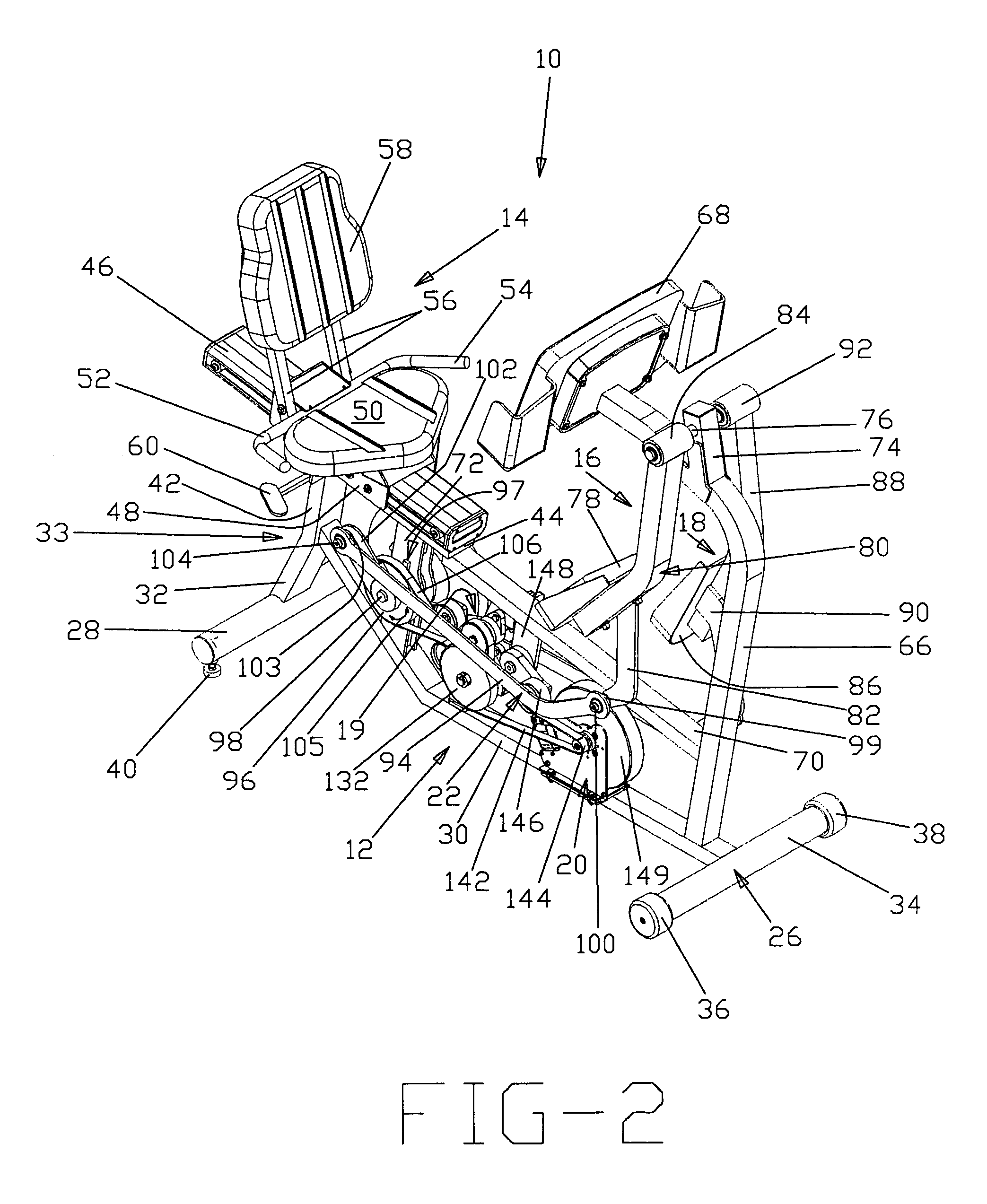
[0025]Referring now to FIGS. 1–4, a seated stepper 10 for providing muscular and cardiovascular conditioning of the lower body comprises a frame 12, a seat 14 adjustably secured to the frame 12, respective right and left foot lever arrangements 16, 18 pivotally joined to the frame and generally horizontally displaced from seat 14, a transmission arrangement 19, a single resistance structure 20, and right and left foot motion transfer systems 22, 24. Generally all the major components of the stepper 10 beneath the seat 14 are enclosed by a lower housing (not shown) that prevents inadvertent contact with the exerciser or the exerciser's clothing during the use of the stepper 10.

[0026]Frame 12 includes a front transverse member 26, a rear transverse member 28 and a longitudinally extending member 30 which extends linearly, rearwardly and angularly upwardly from the front transverse member 26 and terminates in a strut 33 having a lower branch 32 fixed to the center of the rear transvers...


PUM


Abstract

The seated stepper is provided for exercising the lower body. The stepper includes a frame having opposite sides and a longitudinal axis, and a seat attached to the frame. First and second foot lever arrangements are pivotally coupled together on opposite sides of the frame to move alternately in forward and rearward directions towards forward and rearward positions. The foot lever arrangements have linearly moveable right and left foot receptacles adapted to be engaged by an exerciser's feet. First and second motion transfer arrangements are mounted on opposite sides of the frame and coupled to the foot lever arrangements for enabling reciprocating movement of one foot lever arrangement relative to the other foot lever arrangement. A transmission arrangement is mounted on the frame and is operably connected to the first and second motion transfer arrangements. The transmission arrangement includes upper and lower pulley and gear trains in meshing relationship with one another. A resistance structure is mounted to the frame and is operably connected to the transmission arrangement for resisting pivotal movement of each foot lever arrangement in one of the forward and rearward directions. The transmission arrangement enables either of the foot receptacles to be moved and prevents any inertia from the resistance structure from being transferred back to the foot lever arrangements.

Description

FIELD OF THE INVENTION[0001]This invention relates generally to exercise equipment for strengthening muscles and providing cardiovascular conditioning. More particularly, the invention pertains to a stepper for permitting exercising of the lower body while the exerciser maintains a seated position.BACKGROUND OF THE INVENTION[0002]One of the more popular exercise devices in widespread use today is a seated or recumbent stepper which provides aerobic exercise as well as development of the leg muscles. Such device combines the comfort and support of a seated or reclined exercise position with a striding type of exercise such as provided by conventional upright machines known to simulate stair climbing.[0003]One of the concerns of steppers relates to the application of resistance and its role in maintaining a smooth, rhythmic motion through the course of an exercise session. Some steppers provide non-uniform or variable resistance because of the use of chains, cables and springs which d...

Claims


Application Information

Patent Timeline
IPC IPC(8): A63B21/00A63B69/06A63B21/005A63B23/04
CPCA63B22/0023A63B22/0664A63B21/0051A63B2022/067A63B2208/0238A63B2225/09A63B2225/68A63B2225/687
Inventor ELLIS, PATRICK D.
Owner NORTHLAND INDS
Learn More