Supercharge Your Innovation With Domain-Expert AI Agents!

Rotor assembly for dynamo electric machines

Active Publication Date: 2005-08-23
SAFRAN POWER UK
View PDF7 Cites 29 Cited by
  • Summary
  • Abstract
  • Description
  • Claims
  • Application Information

AI Technical Summary

Benefits of technology

[0005]In accordance with a first aspect of the present invention there is provided a rotor assembly for a dynamo electric machine, the rotor assembly comprising a rotor core incorporating radially extending rotor poles, rotor windings encircling respective rotor poles, circumferentially extending pole tips at the outer end of each pole respectively, said tips overlying the rotor winding encircling the respective pole, a plurality of rotor slot closure members, each closure member spanning the gap between a pair of adjacent poles, and including lateral flanges interposed between the respective rotor windings and the associated pole tips, a spacer member positioned beneath each closure member and engaging the radially extending faces of the adjacent windings, and, a locking wedge assembly comprising a pair of tapering locking wedges extending axially of the rotor assembly between each closure member and the associated spacer, the locking wedges extending with their tapers in opposite directions so that moving the wedges longitudinally towards one another increases the radial dimension of the combination of the locking wedges driving the associated spacer and closure apart in a radial direction.

Problems solved by technology

A recognised problem in the construction of dynamo electric machine rotors, is that the rotor windings, which encircle the radially extending poles of the rotor, must be held securely within the rotor core not only against vibration, but more particularly against centrifugal forces which are exerted on the windings throwing the windings radially outwardly as the rotor rotates.

Method used


Image

  • Rotor assembly for dynamo electric machines
  • Rotor assembly for dynamo electric machines
  • Rotor assembly for dynamo electric machines

Examples


Embodiment Construction

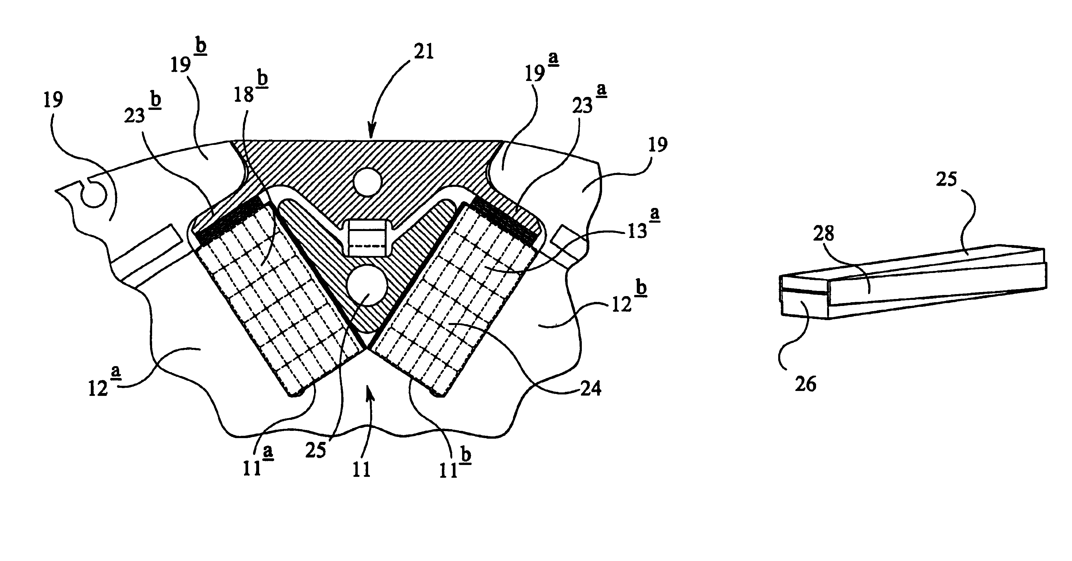
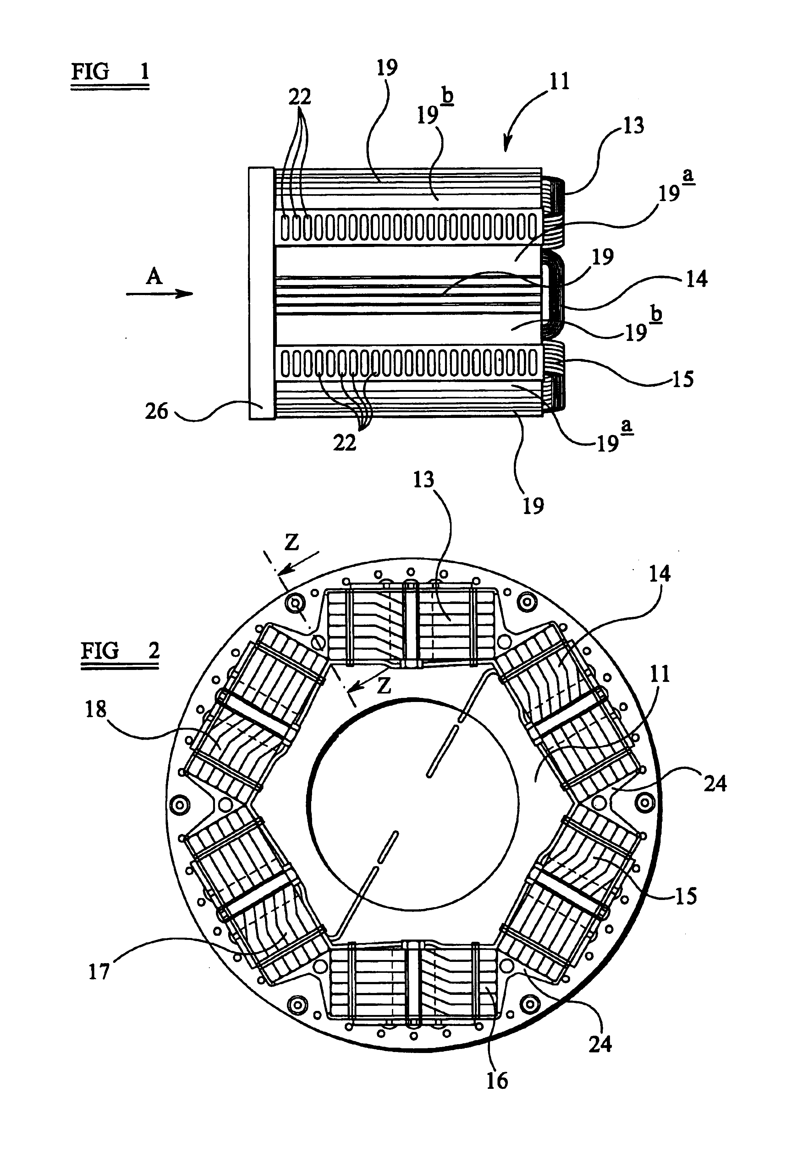
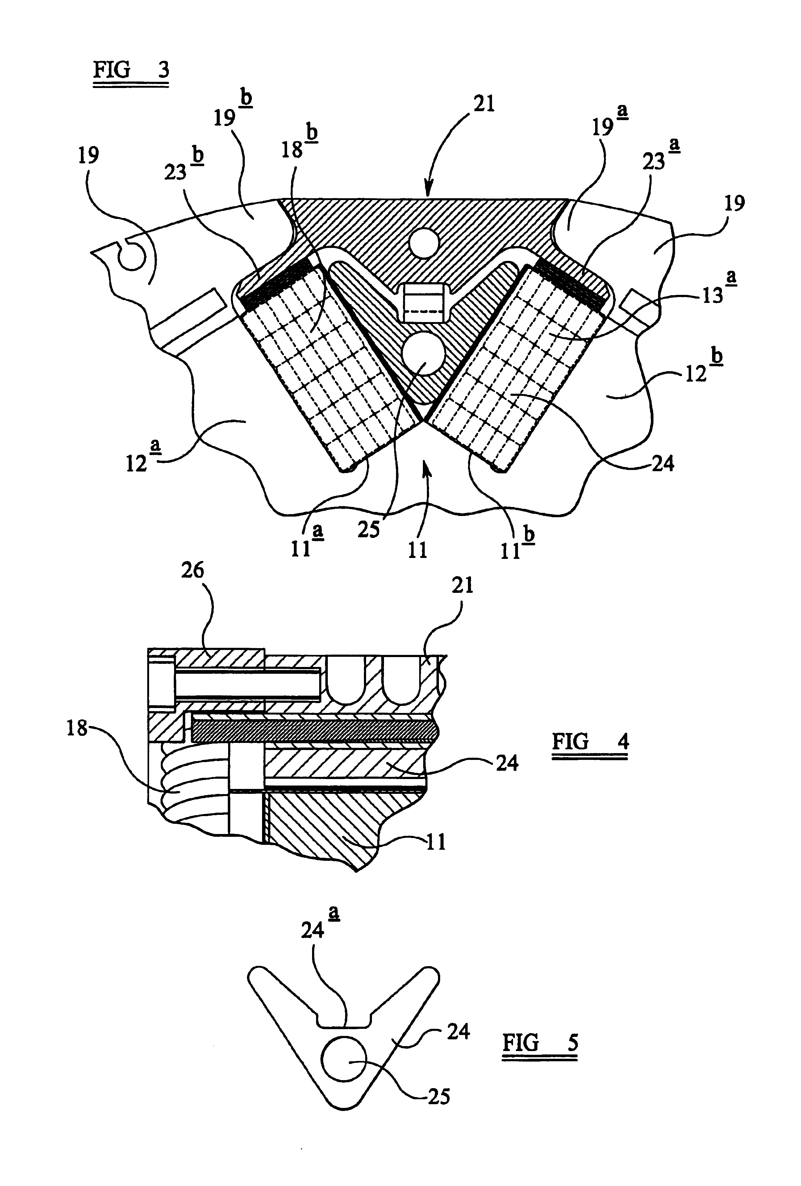
[0027]Referring to the drawings, the rotor assembly includes an elongate generally cylindrical body or rotor core which, in use, is mounted on a rotor shaft for rotation therewith about the axis of the rotor shaft within a corresponding stator assembly. The construction of the rotor core is not of particular significance to the present invention, and it will be recognised that the rotor core may be formed from a plurality of laminae if desired. The rotor core described herein is laminated and FIG. 10 illustrates one of the laminae, a plurality of which are stacked in face to face alignment and secured together in a conventional manner. The rotor core includes six equiangularly spaced radially extending integral poles 12 two of which are seen in part in FIG. 3 where they are identified by the reference numerals 12a and 12b respectively. The poles 12 are of rectangular cross-section and so define between them generally V-shaped rotor slots.

[0028]Each pole is encircled by a rotor windi...


PUM


Abstract

A rotor assembly for a dynamo electric machine, the rotor assembly comprising a rotor core incorporating radially extending rotor poles, rotor windings encircling respective rotor poles, circumferentially extending pole tips at the outer end of each pole respectively, said tips overlying the rotor winding encircling the respective pole, a plurality of rotor slot closure members, each closure member spanning the gap between a pair of adjacent poles, and including lateral flanges interposed between the respective rotor windings and the associated pole tips, a spacer member positioned beneath each closure member and engaging the radially extending faces of the adjacent windings, and, a locking wedge assembly comprising a pair of locking wedges extending axially of the rotor assembly between each closure member and the associated spacer, the locking wedges extending with their tapers in opposite directions so that moving the wedges longitudinally towards one another increases the radial dimension of the combination of the locking wedges driving the associated spacer and closure apart in a radial direction. Also disclosed is a method of manufacturing a rotor assembly.

Description

TECHNICAL FIELD[0001]This invention relates to a high rotational speed rotor assembly for a dynamo electric machine, particularly, but not exclusively, a high rotational speed generator for use in conjunction with an aircraft gas turbine engine, and to a method of manufacturing such a rotor assembly.BACKGROUND ART[0002]A recognised problem in the construction of dynamo electric machine rotors, is that the rotor windings, which encircle the radially extending poles of the rotor, must be held securely within the rotor core not only against vibration, but more particularly against centrifugal forces which are exerted on the windings throwing the windings radially outwardly as the rotor rotates. These problems are recognised in high speed machines where the rotor rotates very rapidly, and are exacerbated by increasing the rotor diameter for example to increase the power output of a generator.[0003]The poles of the core of the rotor extend radially outwardly with respect to the rotationa...

Claims


Application Information

Patent Timeline
IPC IPC(8): H02K3/52H02K3/46
CPCH02K3/527
Inventor BUCHAN, NEIL FERGUSFAKULT, JOSEPH PAUL
Owner SAFRAN POWER UK
Features
  • R&D
  • Intellectual Property
  • Life Sciences
  • Materials
  • Tech Scout
  • Unparalleled Data Quality
  • Higher Quality Content
  • 60% Fewer Hallucinations
Learn More