Supercharge Your Innovation With Domain-Expert AI Agents!

Axial flow fan for external rotor

a technology of axial flow fan and external rotor, which is applied in the direction of liquid fuel engine, vessel construction, marine propulsion, etc., can solve the problems of low production efficiency, high production cost, and inability to install this axial flow fan reliably, and achieves high production efficiency, simple assembly, and reliable connection

Inactive Publication Date: 2011-01-27
ZHONGSHAN BROAD OCEAN
View PDF8 Cites 0 Cited by
  • Summary
  • Abstract
  • Description
  • Claims
  • Application Information

AI Technical Summary

Benefits of technology

[0006]In view of the above-described problem, it is one objective of the invention to provide an axial flow fan for an external rotor that features simple assembling, high production efficiency, reliable connection, and low production cost.
[0027]Advantages of the invention are as follows: 1) the annular cylinder on the support is fit on the housing of the external rotor of the external rotor motor, and the inner wall of the annular cylinder is interference-fit with the outer wall of the external rotor, which results in simple assembling, reliable connection, high production efficiency, low requirement for workers, and low production cost; and 2) the external convex ring disposed between the annular cylinder and the installation pin is capable of increasing radial dimension and ensuring stable force transfer.

Problems solved by technology

However, requirements for a welding position and a welding direction of the air blade are stringent, and a high-level welding technology is needed, which cause high production cost and low production efficiency.
A different structure employs a groove disposed on an outer surface of the housing, but installation of this axial flow fan is not reliable.

Method used


Image

  • Axial flow fan for external rotor
  • Axial flow fan for external rotor
  • Axial flow fan for external rotor

Examples


first embodiment

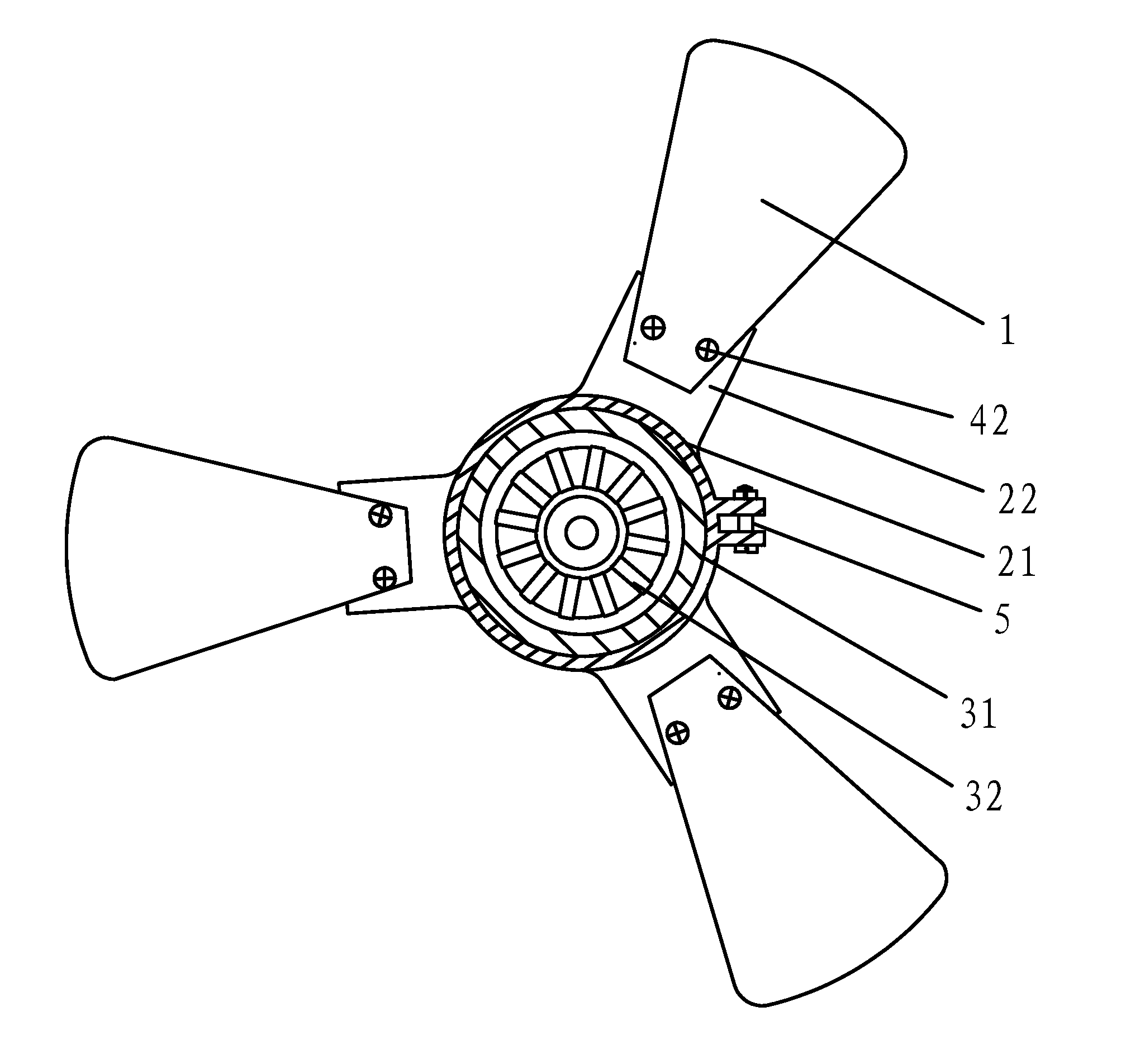
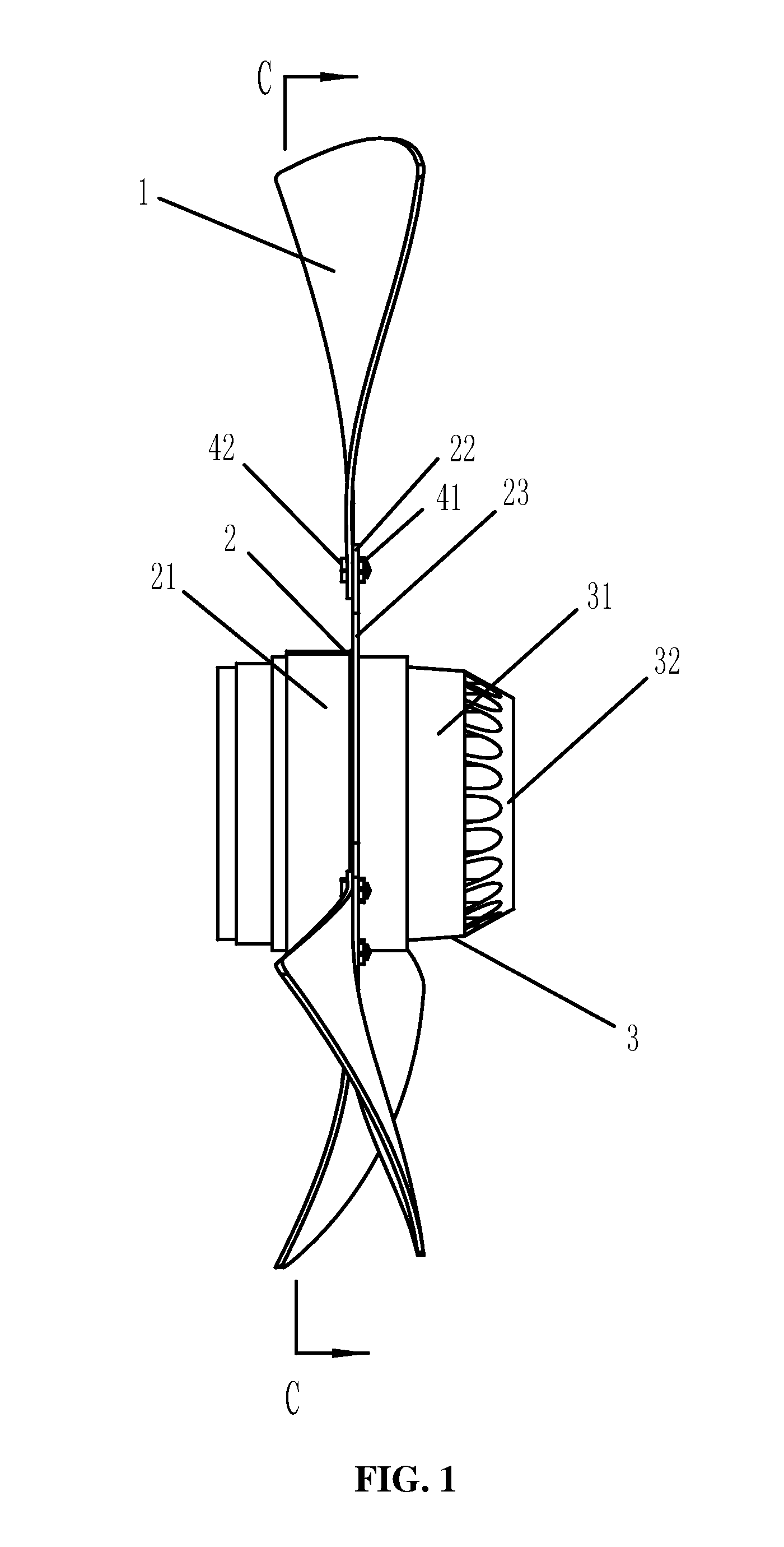
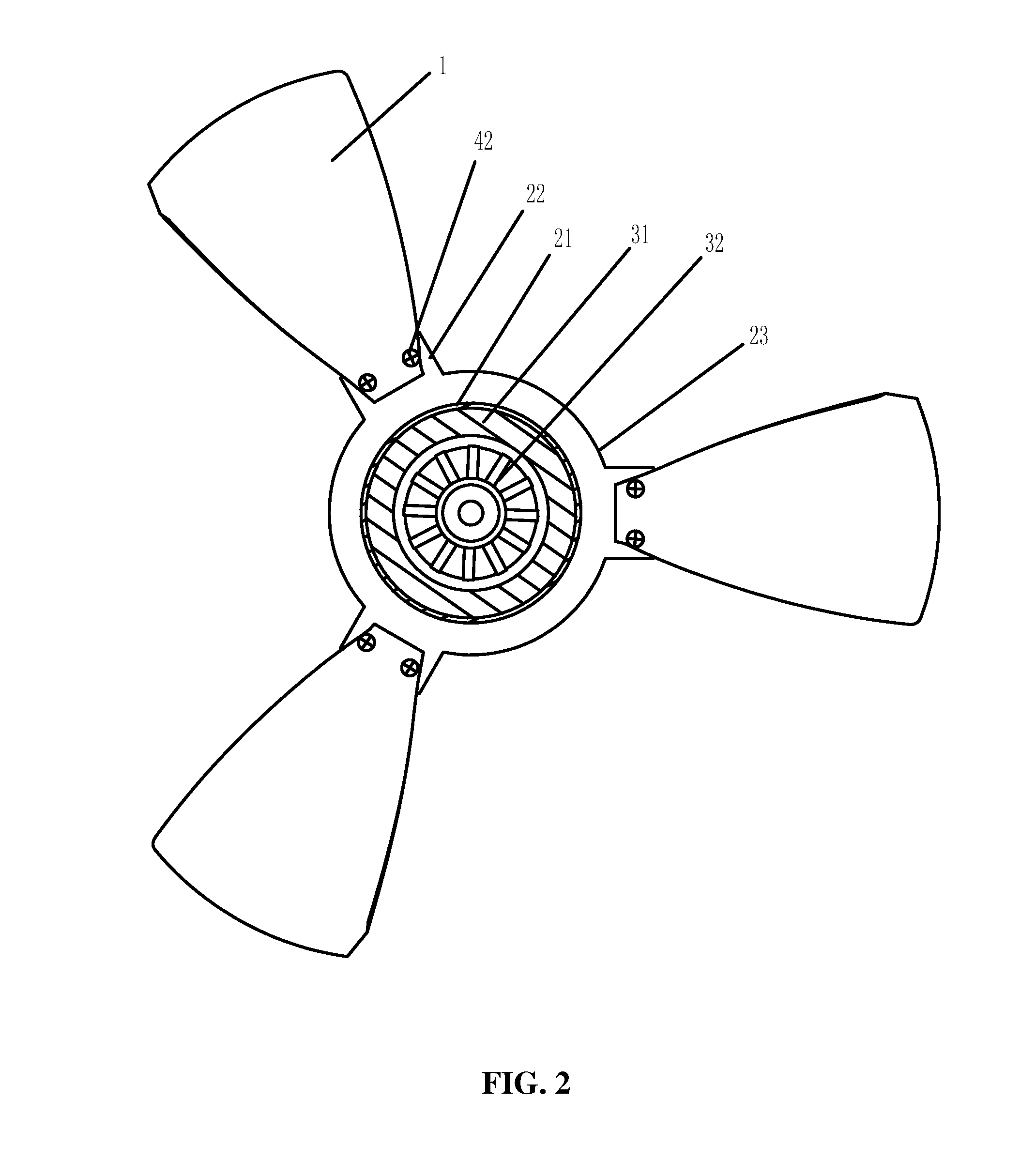
[0033]As shown in FIGS. 1 and 2, an axial flow fan for an external rotor of the invention comprises an axial flow blade 1, a support 2 comprising an annular cylinder 21 and multiple installation pins 22, an external rotor motor 3 comprising an external rotor 31 and an inner stator 32, and an external convex ring 23.

[0034]The installation pins 22 are extended from the outside of the annular cylinder 21.

[0035]The axial flow blade 1 is disposed on the installation pin 22.

[0036]The annular cylinder 21 is fit on the external rotor 31 of the external rotor motor 3, and is integrally formed.

[0037]The external convex ring 23 is disposed between the annular cylinder 21 and the installation pin 22, and operates to increase radial dimension and to improve structural strength.

[0038]Inner wall of the annular cylinder 21 is interference-fit with outer wall of the external rotor 31.

[0039]A screw hole is disposed on the installation pin 22, and the axial flow blade 1 is disposed on the installation...

second embodiment

[0041]As shown in FIGS. 3 and 4, an axial flow fan for an external rotor of the invention comprises an axial flow blade 1, a support 2 comprising an annular cylinder 21 and multiple installation pins 22, and an external rotor motor 3 comprising an external rotor 31 and an inner stator 32.

[0042]The installation pins 22 are extended from the outside of the annular cylinder 21.

[0043]The axial flow blade 1 is disposed on the installation pin 22.

[0044]The annular cylinder 21 is fit on the external rotor 31 of the external rotor motor 3, and is formed by an annular body with an opening via a fastening device 5 or via welding.

[0045]Inner wall of the annular cylinder 21 is interference-fit with outer wall of the external rotor 31.

[0046]A screw hole is disposed on the installation pin 22, and the axial flow blade 1 is disposed on the installation pin 22 via nuts 42 and bolts 41. Alternatively, a through hole is disposed on the installation pin 22, and the axial flow blade 1 is disposed on th...


PUM


Abstract

An axial flow fan for an external rotor, including at least: an axial flow blade, a support comprising an annular cylinder and multiple installation pins, and an external rotor motor comprising an external rotor. The installation pins are extended from the outside of the annular cylinder. The axial flow blade is disposed on the installation pin. The annular cylinder is fit on the external rotor of the external rotor motor. The flow fan features simple and convenient assembling, reliable connection, high production efficiency, low requirement for workers, and low production cost.

Description

CROSS-REFERENCE TO RELATED APPLICATIONS[0001]Pursuant to 35 U.S.C. §119 and the Paris Convention Treaty, this application claims the benefit of Chinese Patent Application No. 200920061726.0 filed on Jul. 27, 2009, the contents of which are incorporated herein by reference.BACKGROUND OF THE INVENTION[0002]1. Field of the Invention[0003]The invention relates to an axial flow fan, and more particularly to an axial flow fan for an external rotor.[0004]2. Description of the Related Art[0005]A typical structure for a conventional axial flow fan for an external rotor includes an air blade that is welded with external surface of a housing of the external rotor. However, requirements for a welding position and a welding direction of the air blade are stringent, and a high-level welding technology is needed, which cause high production cost and low production efficiency. A different structure employs a groove disposed on an outer surface of the housing, but installation of this axial flow fan...

Claims


Application Information

Patent Timeline
Patent Type & Authority Applications(United States)
IPC IPC(8): F04D29/34F04D29/38
CPCF04D29/34
Inventor NING, HUASHENG
Owner ZHONGSHAN BROAD OCEAN
Features
  • R&D
  • Intellectual Property
  • Life Sciences
  • Materials
  • Tech Scout
  • Unparalleled Data Quality
  • Higher Quality Content
  • 60% Fewer Hallucinations
Learn More