Diagnostic method for an electric drive assembly

a technology of electric drive and diagnostic method, which is applied in the direction of motor/generator/converter stopper, dynamo-electric converter control, instruments, etc., can solve the problems of reducing the likelihood of production, not completely eliminating the possibility of undesired operation, and unable to produce the desired torque of the electric machine, etc., to achieve the effect of quick and efficient determination

Inactive Publication Date: 2005-08-23
FORD MOTOR CO
View PDF12 Cites 27 Cited by
  • Summary
  • Abstract
  • Description
  • Claims
  • Application Information

AI Technical Summary

Benefits of technology

[0009]The present invention provides a method for quickly and efficiently determining whether an electric drive assembly is providing a desired amount of torque.

Problems solved by technology

The current regulator therefore tends to cause the electric machine to produce a desired amount of torque.
While this strategy does reduce the likelihood of the production of undesired torque, it does not entirely eliminate the possibility of undesired operation.
This strategy also does not ensure that such undesired operation will be recognized in a timely manner by an operator or user of the electric drive assembly since the electrical current regulator does not identify, or make known to the user, the nature of the operation of the electric drive assembly.

Method used


Image

  • Diagnostic method for an electric drive assembly
  • Diagnostic method for an electric drive assembly

Examples


Embodiment Construction

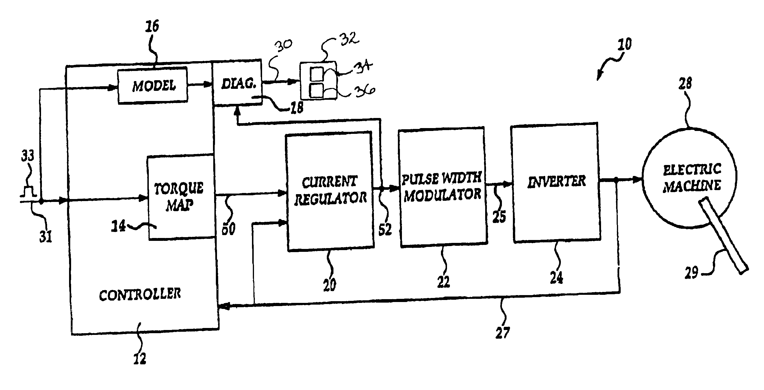
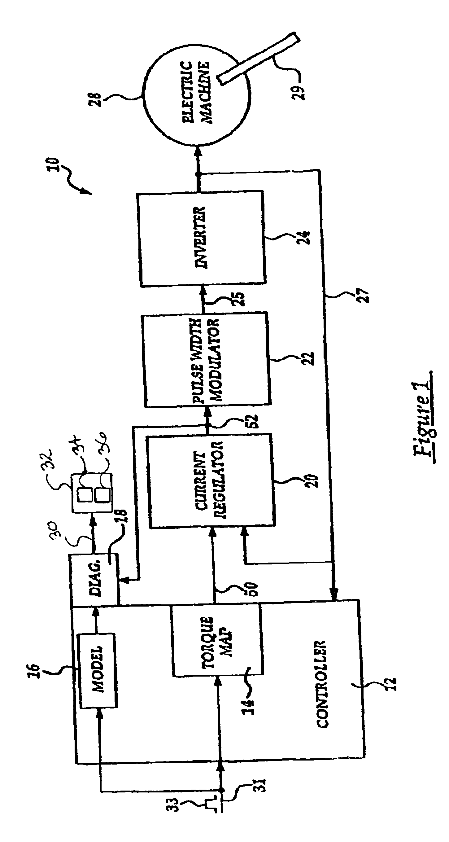
[0016]Referring now to FIG. 1, there is shown an electric drive assembly 10 which is made in accordance with the teachings of the preferred embodiment of the invention. Particularly, the electric drive assembly 10 includes a controller 12 which is operable under stored program control and which may comprise, by way of example and without limitation, a commercially available processor assembly. The controller 12 includes a torque map portion 14, a model portion 16, and a check or consistency / diagnostic portion 18. It should be appreciated that each of these portions 14, 16, 18 may be implemented within software and may be operatively resident within the controller 12 and that, in one non-limiting embodiment, portion 18 may reside outside of the controller 12. It should be further appreciated that the controller 12 may be physically and communicatively coupled to a source of energy (not shown) and is effective, according to the methodology of the invention, to selectively cause the en...


PUM


Abstract

A method and an electrical drive assembly 10 which operates in accordance with the method. Particularly, the drive assembly 10 includes a diagnostic portion 18 which compares a voltage signal which is communicated to an electrical machine 28 and a voltage signal which is selected by use of a desired torque command signal 33 and which provides a diagnostic of the electrical drive assembly 10 based upon the comparison, effective to provide a positive indication to a user of the drive assembly.

Description

BACKGROUND OF INVENTION[0001]1. Field of the Invention[0002]The present invention generally relates to a diagnostic method for determining whether an electric drive assembly is producing a desired amount of torque and to an electric drive assembly which incorporates the method and more particularly, to an electric drive assembly which compares a pair of signals or values in order to determine whether the assembly is producing a desired amount of torque.[0003]2. Background of the Invention[0004]Electric drive assemblies are utilized in a wide variety of applications requiring the selective production of torque. Examples of such applications include, but are not limited to, manufacturing or producing an item or causing selective propulsion. It is desirable to ensure or ascertain whether these electric drive assemblies are desirably providing a required amount of torque.[0005]One strategy to increase the likelihood that a desired amount of torque will be produced by an electric drive a...

Claims


Application Information

Patent Timeline
Patent Type & Authority Patents(United States)
IPC IPC(8): B60L15/20G01M19/00G05D17/02G05D17/00H02P7/00G01M99/00G01R31/34H02P29/00
CPCG01R31/343H02P29/00Y02T10/7258Y02T10/72
Inventor GABRIEL, DAVID CRISTLIANG, FENGDEGNER, MICHAEL W.PRAKASH, RAJSANKARAN, VENKATESWA ANAND
Owner FORD MOTOR CO
Why Eureka
Try Eureka