Vehicle safety system

a safety system and vehicle technology, applied in the field of vehicle safety systems, can solve the problems of motorists at potential risk of property damage, injuries, even fatalities, deceleration, and increase, and achieve the effect of enhancing the safety of boaters in the area

Inactive Publication Date: 2005-08-23
INNERVISION BY HENRY
View PDF31 Cites 36 Cited by
  • Summary
  • Abstract
  • Description
  • Claims
  • Application Information

AI Technical Summary

Benefits of technology

[0008]The present invention is a vehicle safety system used to enhance the safety of motorists, which includes a local unit attached to an associated motor vehicle and one or more remote units portable relative to the motor vehicle. The local unit detects operating conditions of the associated vehicle and emits wireless transmissions based upon the operating conditions detected. Such operating conditions may include activation of a braking system, deceleration, activation of a turn signal, and reverse operation (i.e. backing up). The remote units receive the wireless transmissions and produce warning signals based upon the wireless transmissions received. As such, the remote units act as a wireless devices for producing visible and / or audible warnings based upon the various operating conditions detected.
[0010]The remote unit is portable relative to the personal motor vehicle and may be secured on the rear surface of a helmet, on the back side of a safety jacket, or on any other suitable location. The remote unit receives the wireless transmissions emitted from the local unit regarding the operating conditions of the personal motor vehicle and produces corresponding warning signals. This provides additional visible and / or audible warnings to enhance the safety of the motorist of the personal motor vehicle.
[0014]The remote unit, which may also mounted to the motor boat and connected to the electrical source of the motor boat, receives the wireless transmissions emitted from the local unit regarding the operating conditions of the motor boat and produces corresponding warning signals. As such, the remote unit acts as a warning light for when the motor boat is decelerating or backing up, enhancing the safety of boaters in the area.

Problems solved by technology

Operation of motor vehicles, such as automobiles, trucks, personal motor vehicles, and motor boats, constantly places motorists at potential risk of property damages, injuries, and even fatalities.
Due to the speed and power of motor vehicles, many dangerous situations exist that can result in collisions.
In addition to the common hazards of minimal collision protection, a danger that is becoming more common with newer motorcycles is that, even without braking, they can decelerate very rapidly, almost as fast as braking itself.
This presents a dangerous situation because the brakes are not used.
However, if a motorcycle rapidly decelerates without braking, the brake light will not illuminate to warn others that the motorcycle is slowing down.
Therefore, following traffic are not provided adequate warning of the deceleration.
Motorists are also placed in dangerous situations when they leave their vehicles at night.
If a motorist pulls to the side of a road at night and leaves his or her motorcycle on the side of the road, traffic will only be able to see the lights of the motorcycle.
Oncoming traffic will have little or no warning of the location of the motorist, and therefore, could accidentally hit the motorist.
Another hazardous condition occurs with the use of towed trailers.
Trailers typically obstruct the view of the tail lights of the towing motor vehicles, hindering their view by following traffic.
If a towing motor vehicle brakes or activates a turn signal with obstructed tail lights, the following traffic may not be able to observe the action.
This could result in dangerous and expensive collisions.
Moreover, not all trailers include built-in tail lights that directly hook into the towing vehicles tail light system via wire cables.
Additionally, motor boats do not have braking systems for slowing down.
If a motor boat rapidly decelerates, following boaters will have little warning to avoid potentially dangerous and expensive collisions.

Method used


Image

  • Vehicle safety system
  • Vehicle safety system
  • Vehicle safety system

Examples


first embodiment

[0089]FIGS. 5a and 5b are block diagrams of remote unit 22 and local unit 20, illustrating an additional concept of the present invention. The additional concept includes the use of a two-way voice communication system that incorporates many of the components of local unit 20 and remote unit 22. It is a hands-free voice communication system that allows riders to talk to each other when each rider wears a helmet 18 incorporating a remote unit 22.

[0090]As illustrated in FIG. 5a, the two-way voice communication system includes microphone / earpiece 61, which is worn by motorist 16 under helmet 18, and is a conventional microphone / earpiece system, such as a cellular phone microphone and earpiece headset. Microphone / earpiece 61 plugs into remote unit 22, connecting microphone / earpiece 61 to remote unit microcontroller 64 for sending and receiving signals to and from remote unit microcontroller 64. When motorist 16 speaks into the microphone of microphone / earpiece 61, a corresponding signal...

second embodiment

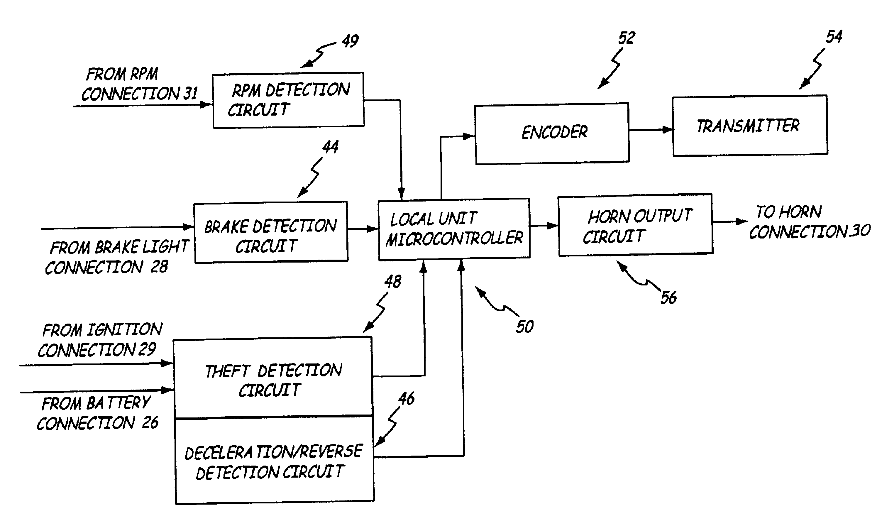
[0158]For an example of an application of the present invention, assume that vehicle 68 decelerates without the brakes of vehicle 68 being activated. Deceleration detection circuit 154 measures and calculates the corresponding inertial forces, and sends signals regarding the inertial forces to local unit microcontroller 116. Local unit microcontroller 116 then compares the inertial forces to the deceleration force threshold. If vehicle 68 is decelerating fast enough so that the inertial force is greater than the deceleration force threshold, then local unit microcontroller 116 produces an output to encoder 118 that vehicle 68 is decelerating. Encoder 118 then digitally encodes the signal and sends the encoded signal to transmitter 120. Transmitter 120 then emits the encoded signal from local unit 74 as a wireless transmission.

[0159]The wireless transmission is intercepted by receiver 122 in both left remote unit 76 and right remote unit 78, and decoded by decoder 124 in each remote ...

third embodiment

[0197]For an example of an application of the present invention, assume that boat 128 decelerates rapidly. Deceleration detection circuit 164 measures and calculates the corresponding inertial forces, and sends signals regarding the inertial forces to local unit microcontroller 168. Local unit microcontroller 168 then compares the inertial forces to the deceleration force threshold. If boat 128 is decelerating fast enough so that the inertial force is greater than the deceleration force threshold, then local unit microcontroller 168 produces an output to encoder 170 that boat 128 is rapidly decelerating. Encoder 170 then digitally encodes the signal and sends the encoded signal to transmitter 172. Transmitter 172 then emits the encoded signal from local unit 134 as a wireless transmission.

[0198]The wireless transmission is intercepted by receiver 174 in remote unit 136 and decoded by decoder 176. The decoded signal is then sent from decoder 176 to remote unit microcontroller 178. Re...


PUM


Abstract

A vehicle safety system used to enhance the safety of motorists by emitting warning signals from a remote unit. The vehicle safety system incorporates a local unit attached to an associated vehicle that detects the operating conditions of the associated vehicle and emits wireless transmissions of the operating conditions to the remote unit, which is removable and portable relative to the associated vehicle. Upon receiving the wireless transmissions, the remote unit produces warning signals based upon the wireless transmissions received.

Description

CROSS-REFERENCE TO RELATED APPLICATION(S)[0001]None.BACKGROUND OF THE INVENTION[0002]The present invention relates to vehicle safety systems for motorists. In particular the present invention relates to a safety system for detecting operating conditions of an associated vehicle and for emitting corresponding visual and / or audible warning signals from portable locations.[0003]Operation of motor vehicles, such as automobiles, trucks, personal motor vehicles, and motor boats, constantly places motorists at potential risk of property damages, injuries, and even fatalities. Due to the speed and power of motor vehicles, many dangerous situations exist that can result in collisions. For example, operators of personal motor vehicles, such as motorcycles, have inherent safety concerns normally not associated with other vehicles. In addition to the common hazards of minimal collision protection, a danger that is becoming more common with newer motorcycles is that, even without braking, they c...

Claims


Application Information

Patent Timeline
Patent Type & Authority Patents(United States)
IPC IPC(8): B60R25/10B62J27/00
CPCB60R25/1004B60R25/102B62J27/00B60R2325/304B60R2325/306B62J3/14B62J6/045B62J6/26
Inventor HENRY, JOHN JUNIOR
Owner INNERVISION BY HENRY
Why Eureka
Try Eureka