Air feeding apparatus

a technology of air feeding and air feeding rod, which is applied in the direction of lighting and heating apparatus, fluid mattresses, heating types, etc., can solve the problems of inability to carry, reduce the performance of electric fans, and inability to carry, so as to achieve the effect of less power, easy to carry, and strong heating

Inactive Publication Date: 2005-08-30
CHIU KUANG HSING
View PDF5 Cites 32 Cited by
  • Summary
  • Abstract
  • Description
  • Claims
  • Application Information

AI Technical Summary

Benefits of technology

[0007]It is another object of the present invention to provide an air feeding apparatus, which includes cold producing plates disposed in a chamber, which are connected to a switching circuit controllable for changing a working mode of the plates from a cold producing one to a heat producing one; thus, the present apparatus can provide cool in summer and warmth in winter.
[0008]It is yet another object of the present invention to provide additional heating device such as ceramic heating tube to the present air feeding apparatus so that the heating effect can be stronger.
[0009]It is still another object of the present invention to provide an air feeding apparatus, which has a conduit connected to an outlet thereof so that air can be conveyed to any desired locations or other objects, e.g. an inflatable mattress, according to needs, and which consumes less power than conventional air conditioners, and is compact, and light in weight to be easily carried.

Problems solved by technology

However, performance of electric fans is significantly reduced in hot weather.
And, air conditioners are relatively expensive, and cannot be carried.
In addition, central air conditioning systems are only suitable for large buildings such as hospitals and commercial centers.

Method used


Image

  • Air feeding apparatus
  • Air feeding apparatus
  • Air feeding apparatus

Examples


Embodiment Construction

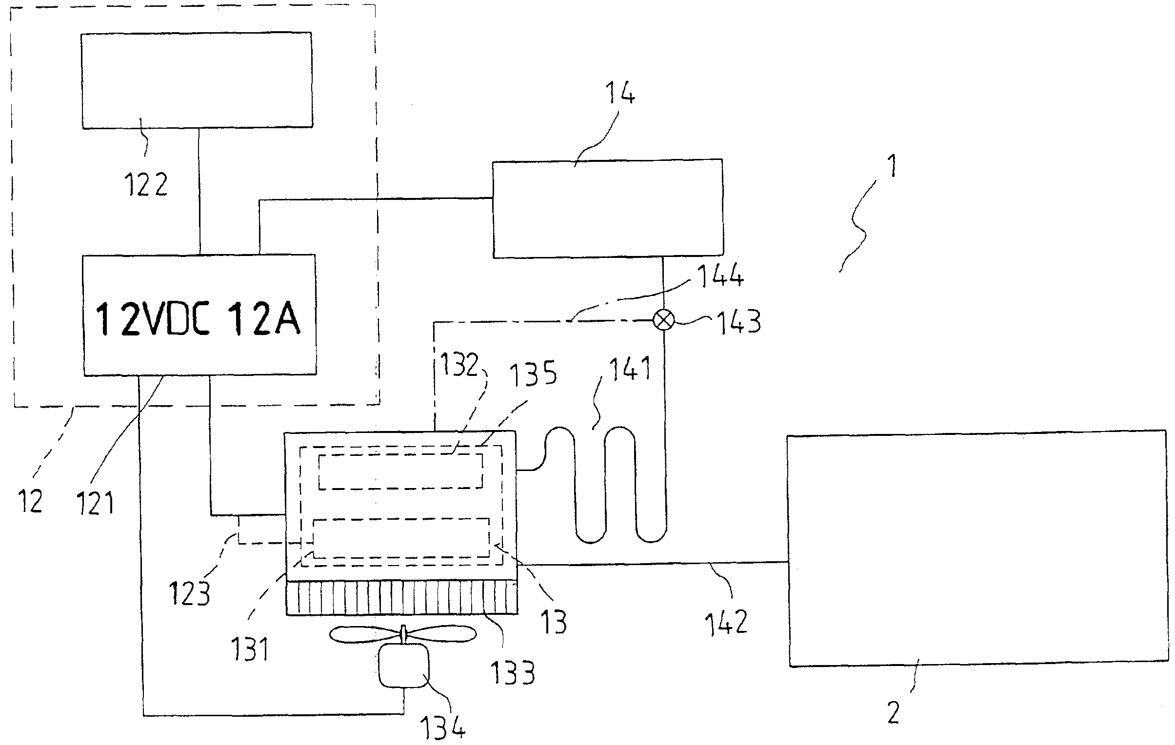
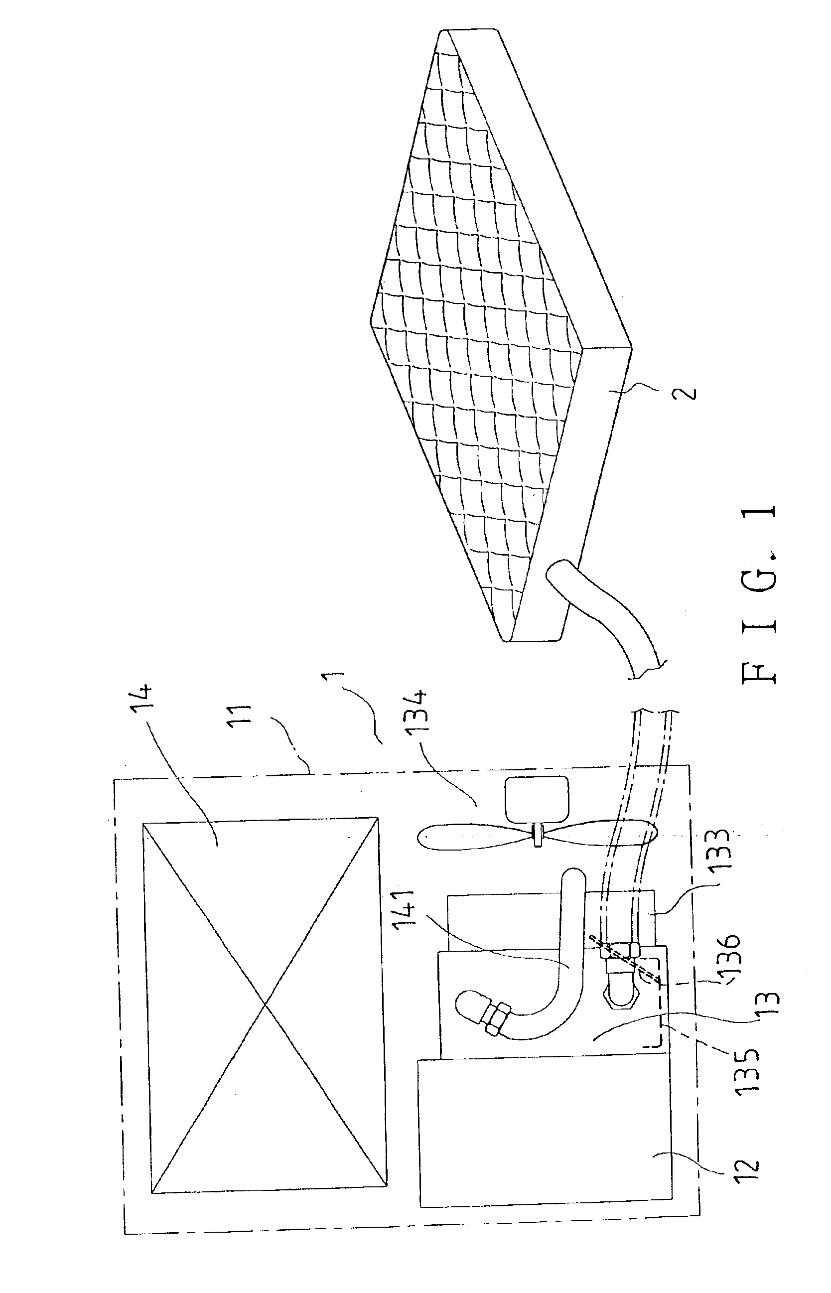
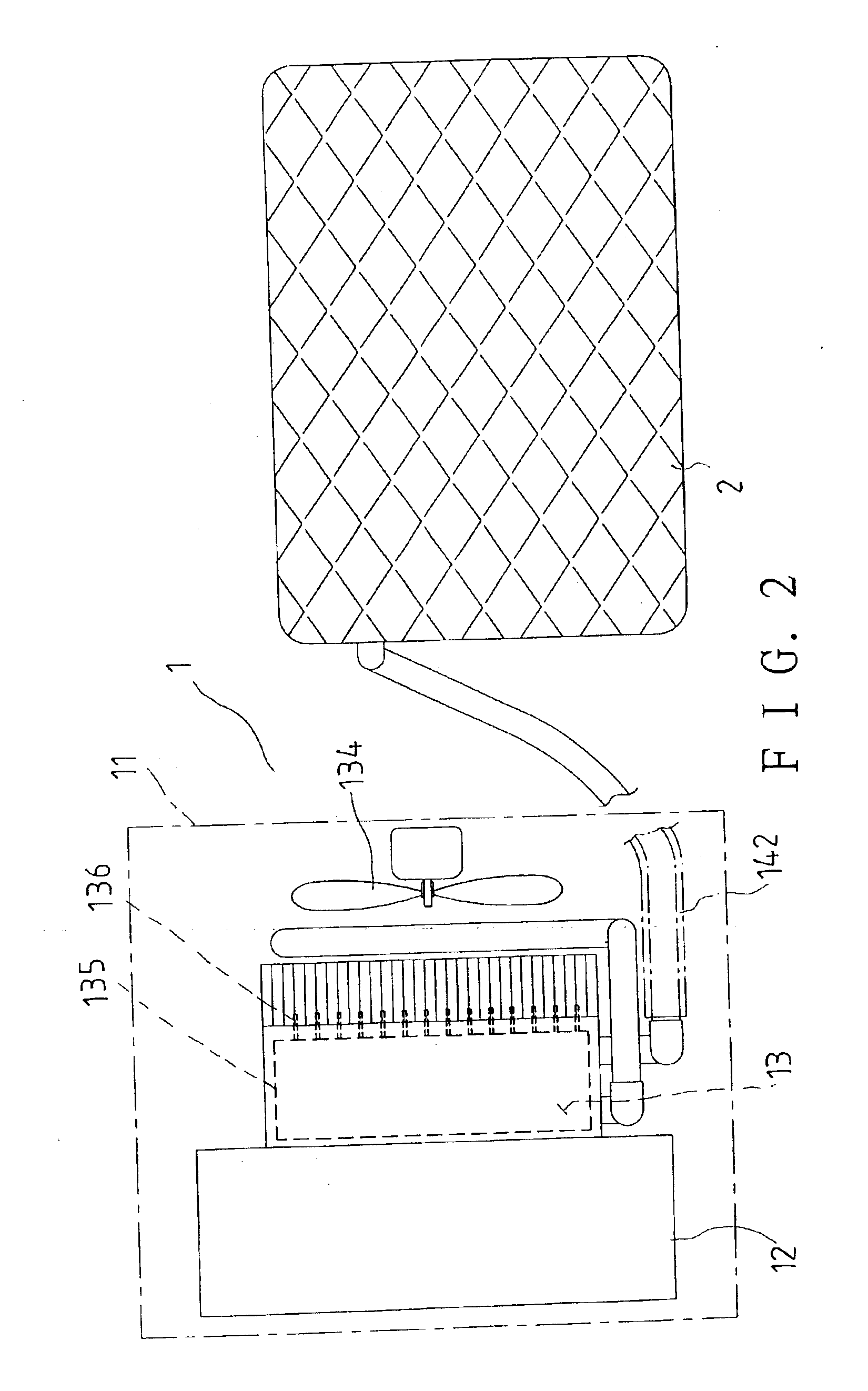
[0014]Referring to FIGS. 1, 2, and 3, a preferred embodiment 1 of an air feeding apparatus in the present invention includes a main housing 11, a control box 12, air supplying chamber 13, and an air pump 14 as main parts.

[0015]A power supplier 121 is disposed in the housing 12, and has a switch 122 for controlling on and off of power. The switch 122 can be of a manual control type or a remote control type used together with a remote control (not shown).

[0016]A cold producing plate 131 as well as a ceramic heating tube 132 are disposed in the air supplying chamber 13 while heat dissipating fins 133 and an electric cooling fan 134 are disposed outside the air supplying chamber 13. A water collecting dish 135 is disposed under the cold producing plates 131 for collecting condensed water formed on the plate 131. Capillaries 136 are provided for conveying water collected in the dish 135 to the heat dissipating fins 133. And, the cooling fan 134 can work to move cool air onto the heat dis...


PUM


Abstract

An air feeding apparatus includes an air supplying chamber disposed in a housing, and cold producing plates in the chamber, which are connected to a switching circuit controllable for changing a working mode of the plates from a cold producing one to a heat producing one. A conduit is connected to an outlet of the air supplying chamber, and sticks outside the housing. Air is forced to travel through the air supplying chamber by means of an air pump, and is guided to outside by means of the conduit; thus, the air traveling through the chamber can have temperature changed by the cold producing plates, and can be conveyed to desired locations or into other objects for use.

Description

BACKGROUND OF THE INVENTION[0001]1. Field of the Invention[0002]The present invention relates to an air feeding apparatus, more particularly one, which can be controlled to change temperature of air supplied from it according to needs.[0003]2. Brief Description of the Prior Art[0004]In early time when air conditioners were not available, electric fans were used to increase ventilation to reduce high temperature in the summer, and stoves were used to produce heat in the winter. Nowadays, air conditioners and electric heating devices are easily available, and many large buildings are equipped with central air conditioning systems therefore people live in a more comfortable environment from the point of view of temperature control.[0005]However, performance of electric fans is significantly reduced in hot weather. And, air conditioners are relatively expensive, and cannot be carried. In addition, central air conditioning systems are only suitable for large buildings such as hospitals a...

Claims


Application Information

Patent Timeline
Patent Type & Authority Patents(United States)
IPC IPC(8): A47C21/00A47C21/04F24F5/00A47C27/08
CPCA47C21/044A47C27/082F24F5/0042F24F2221/12
Inventor HUANG, FU-AN
Owner CHIU KUANG HSING
Why Eureka
Try Eureka