Low current extended duration spark ignition system

a technology of extended duration and spark ignition, which is applied in the direction of machines/engines, mechanical equipment, instruments, etc., can solve the problems of low electrical current, frequent servicing, and insufficient intensity of spark to fully and completely ignite fuel

Active Publication Date: 2005-08-30
CATERPILLAR INC
View PDF10 Cites 5 Cited by
  • Summary
  • Abstract
  • Description
  • Claims
  • Application Information

AI Technical Summary

Problems solved by technology

High electrical currents may cause relatively fast erosion of the plug at the spark plug gap, thereby requiring frequent servicing of the engine to replace the spark plug.
Low electrical currents, on the other hand, may not initiate a spark with sufficient intensity to fully and completely ignite a fuel within a combustion chamber of the engine.
Accordingly, the secondary side of the circuit may be more complex than necessary and may include duplicate components, thereby increasing the overall cost of the circuit.

Method used


Image

  • Low current extended duration spark ignition system
  • Low current extended duration spark ignition system
  • Low current extended duration spark ignition system

Examples


Embodiment Construction

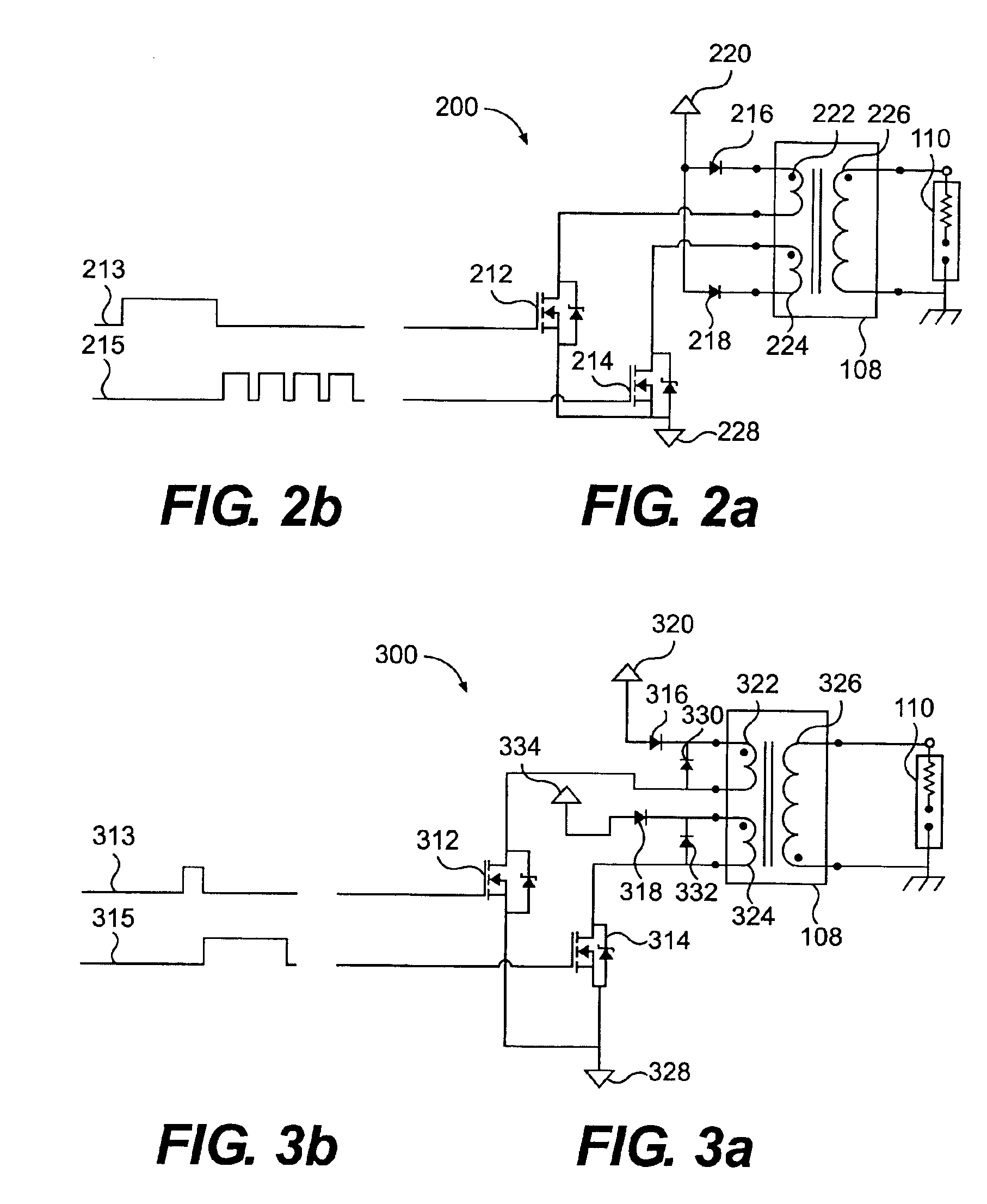
[0020]Wherever possible, the last two digits of each reference number will be used throughout the drawings to refer to the same or like parts. Accordingly, it should be understood that the description of certain components with relation to one exemplary embodiment also applies to the same or like parts included in another exemplary embodiment.

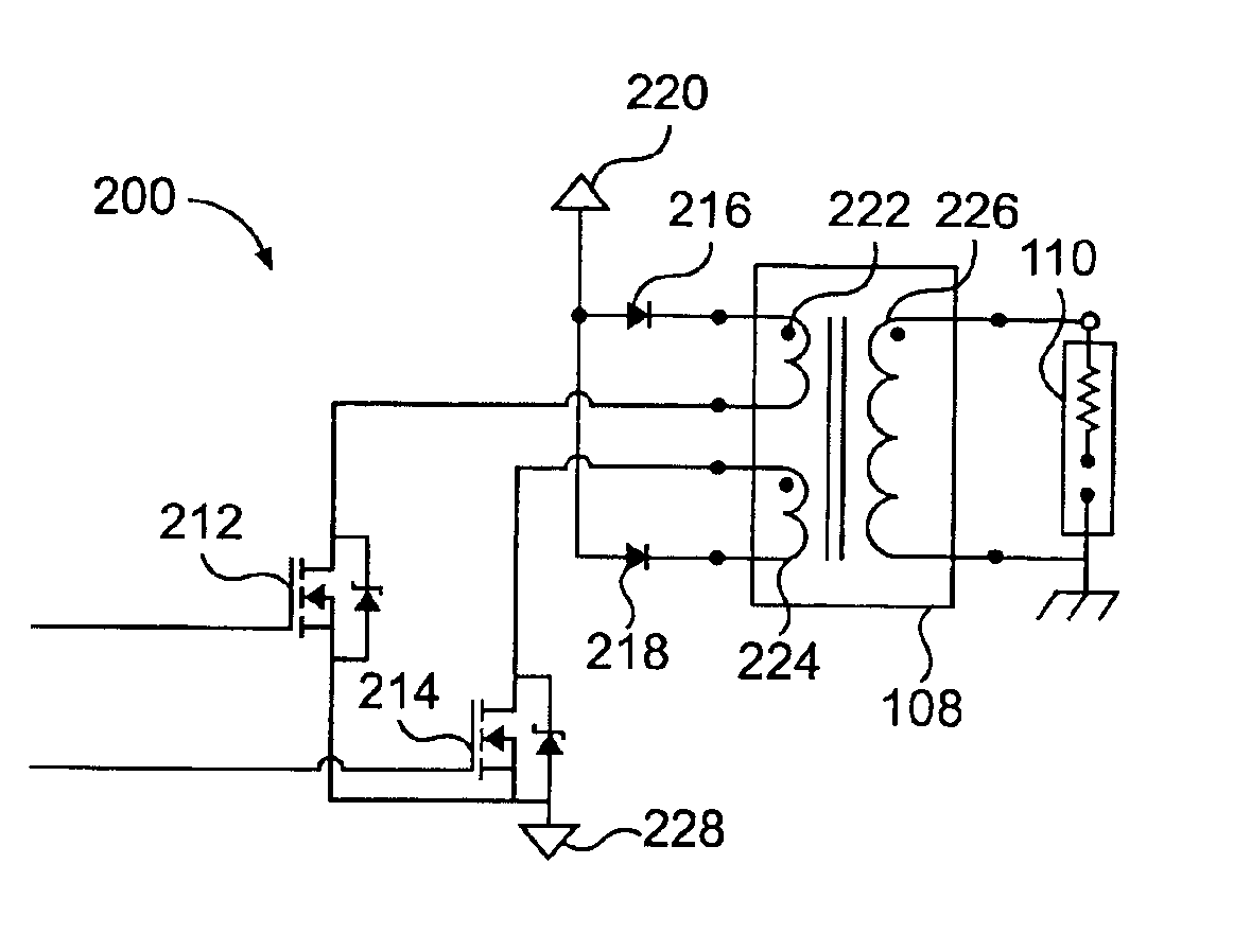
[0021]FIG. 1 is a block diagram of a system 100 for firing a spark plug 110 associated with an engine 101. The system 100 may include a timing controller 102, a drive 104, and an ignition transformer 108. As described in greater detail below, the system 100 is operable to control the intensity and duration of a spark initiated by spark plug 110.

[0022]The spark plug 110 may be any known spark plug that forces a current to arc across a gap. It may also include an electrode at the gap, along with a ceramic insert that ensures that the spark occurs at the electrode tip. The spark plug 110 may require a high voltage to initiate a spark, such as, for...


PUM


Abstract

A system for firing a spark plug is disclosed. The system includes a timing controller configured to send a first timing signal and a second timing signal. The system also includes an ignition transformer having a primary winding and a secondary winding and a spark-plug that is operably associated with the secondary winding. A first switching element is disposed between the timing controller and the primary winding of the ignition transformer. The first switching element controls a supply of power to the primary winding based on the first timing signal. Also, a second switching element is disposed between the timing controller and the primary winding of the ignition transformer. The second switching element controls the supply of power to the primary winding based on the second timing signal. A method for firing a spark plug is also disclosed.

Description

[0001]This invention was made with Government support under DOE Contract No. DE-AC36-83CH10093 awarded by the U.S. Department of Energy. Accordingly, the Government may have certain rights to this invention.TECHNICAL FIELD[0002]This invention relates to a spark ignited engine and, more particularly, to an ignition system for a spark ignited engine.BACKGROUND[0003]The life of a spark plug in an internal combustion engine may be affected by the magnitude of electrical current repeatedly passed across a gap in the spark plug to initiate sparks. High electrical currents may cause relatively fast erosion of the plug at the spark plug gap, thereby requiring frequent servicing of the engine to replace the spark plug. Low electrical currents, on the other hand, may not initiate a spark with sufficient intensity to fully and completely ignite a fuel within a combustion chamber of the engine.[0004]Government regulations are increasingly requiring the use of alternative fuels to reduce polluti...

Claims


Application Information

Patent Timeline
Patent Type & Authority Patents(United States)
IPC IPC(8): F02P3/02F02P3/05F02P3/045
CPCF02P3/0453F02P3/051
Inventor WATERS, STEPHEN HOWARDCHAN, ANTHONY KOK-FAI
Owner CATERPILLAR INC
Why Eureka
Try Eureka