Fiber optic connector with long terminus movement and moderate length

a fiber optic connector and long terminus technology, applied in the direction of optics, instruments, optical light guides, etc., can solve the problem of difficult cleaning of the tip, and achieve the effect of facilitating cleaning of the tip and minimizing the overall length of the connector

Inactive Publication Date: 2005-08-30
ITT MFG ENTERPRISES LLC
View PDF11 Cites 122 Cited by
  • Summary
  • Abstract
  • Description
  • Claims
  • Application Information

AI Technical Summary

Benefits of technology

[0003]In accordance with one embodiment of the present invention, an optic fiber connector is provided, of the type wherein the ferrule is biased to an initial position wherein it projects into an alignment sleeve, which facilitates cleaning of the tip of the ferrule and which minimizes the overall length of the connector. A stop that limits forward movement of the terminus by the spring, positions the tip of the terminus so it lies flush with or slightly forward of the front surface of the surrounding housing front surface. The housing has a peripheral housing portion that projects forward of the ferrule front tip to protect the ferrule tip.

Problems solved by technology

Since the tip of one ferrule lies deep within the alignment sleeve, it can be difficult to clean the tip.

Method used


Image

  • Fiber optic connector with long terminus movement and moderate length
  • Fiber optic connector with long terminus movement and moderate length
  • Fiber optic connector with long terminus movement and moderate length

Examples


Embodiment Construction

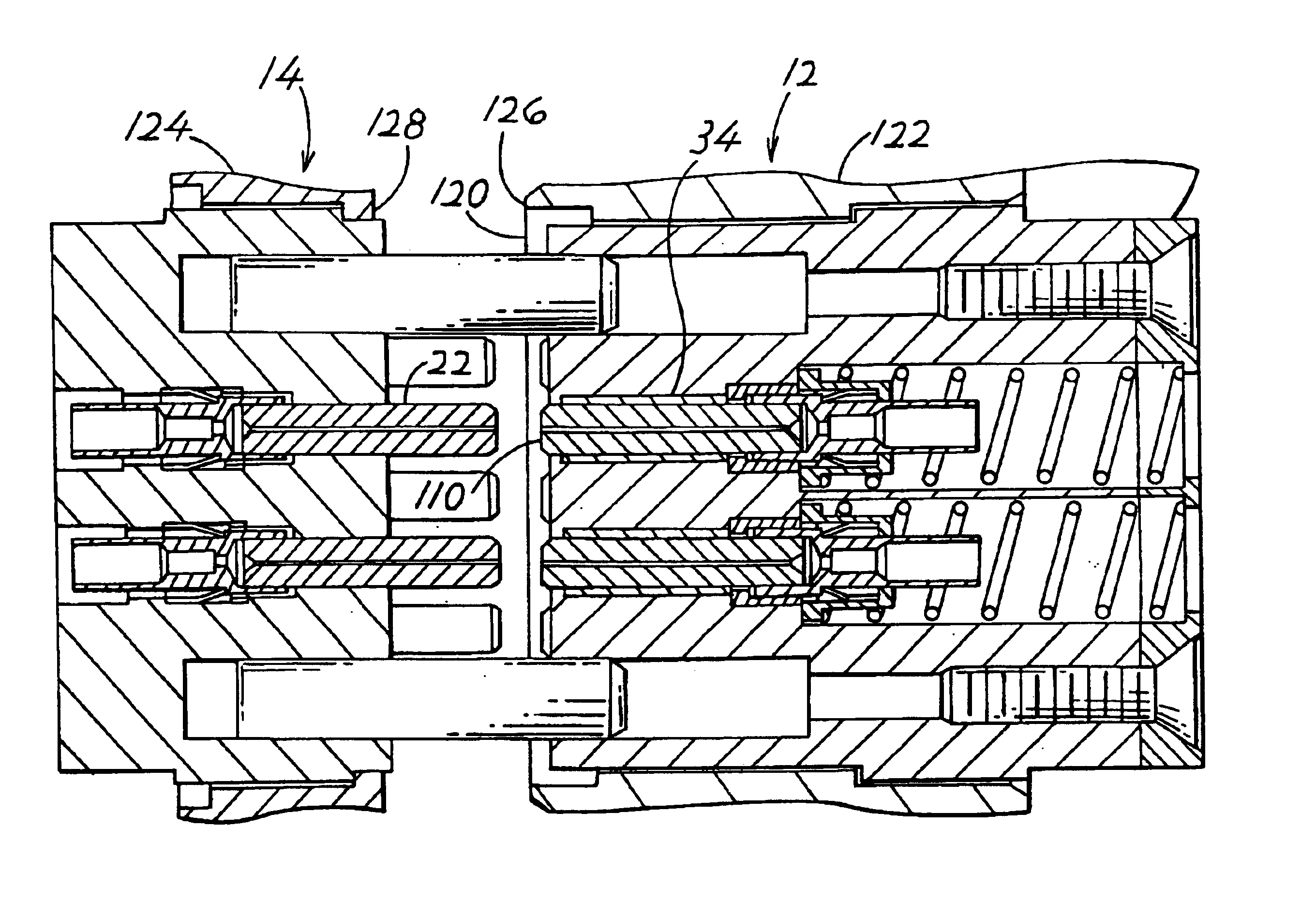
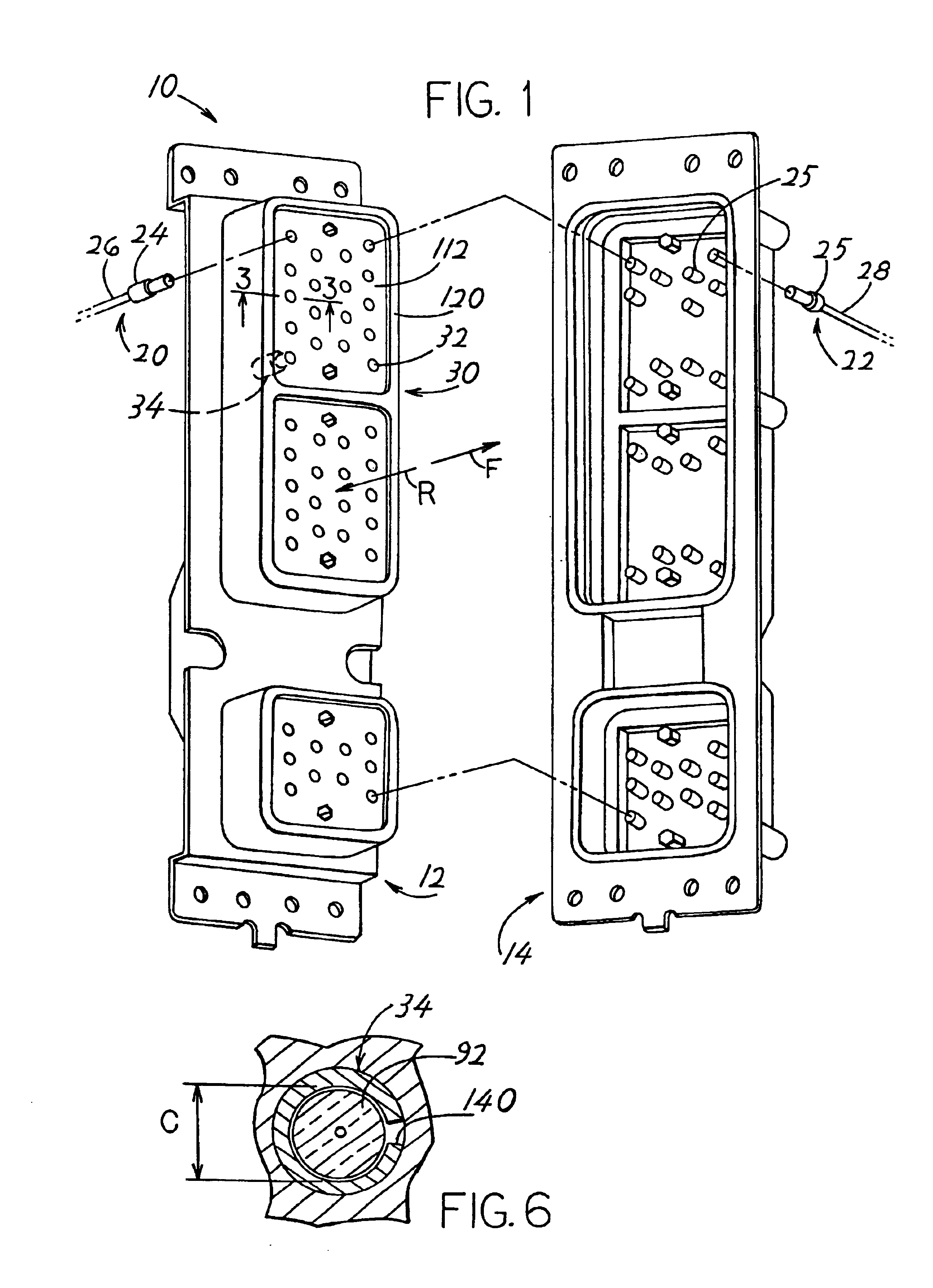
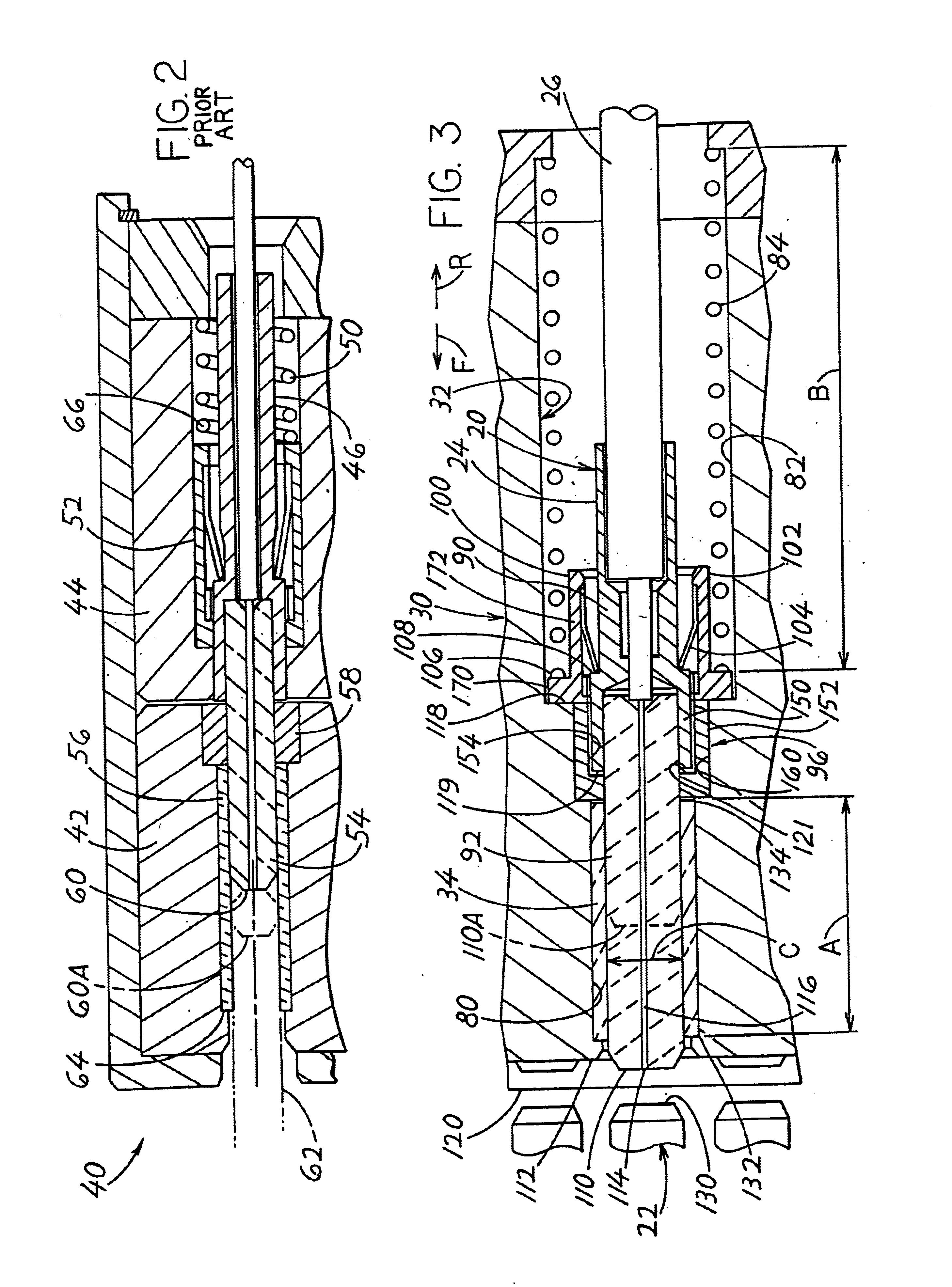
[0013]FIG. 1 illustrates an optic fiber connector system 10 which includes a connector 12 and a mating connector, or connector device 14. Each connector and connector device holds multiple terminus assemblies 20, 22 that each includes a terminus 24, 25 and an optic fiber cable 26, 28. The connector 12 includes a housing 30 with multiple through passages 32 that each extends in forward F and rearward R directions completely through the housing. Each passage holds an alignment sleeve 34, as well as a terminus 24. When the connectors mate, a mating terminus 25 of the connector device 14 projects partially into one of the through passages 32 in the connector, and partially through one of the alignment sleeves 34.

[0014]FIG. 2 illustrates a prior connector 40 that applicant previously designed, which included a housing with front and rear housing parts 42, 44. A terminus 46 was inserted into the rear housing part and biased forwardly by a spring 50 that pushed a retainer 52 forwardly. The...


PUM


Abstract

An optic fiber connector has a terminus (24) with a front tip (110) that lies at an initial position at which the tip is at least flush with or forward of the surrounding housing front surface (112) and which is moved rearwardly by a mating terminus (22) so the tips of the termini are halfway between front and rear ends (132, 134) of an alignment sleeve (34). The housing has a peripheral portion (120) that projects forward of the ferrule front tips to protect them even though they project forward of the housing front surface. The alignment sleeve has a short length (A) that is about three times its inside diameter (C), and a long spring (84) is used to bias the terminus forwardly and maintain a substantially constant forward force on the terminus, the spring having an initial length (B) which is at least 150% of the alignment sleeve length. A plug (96) that holds the alignment sleeve in place, has an internal bore with a rear bore portion (154) that receives the front end of the terminus body (90). A retainer (100) includes a clip holder (102) with a holder rear portion (172) surrounded by the spring.

Description

BACKGROUND OF THE INVENTION[0001]Optic fiber connectors commonly include a housing with one or more through passages that each holds a ferrule that is biased forwardly by a spring. An alignment sleeve may lie at the front of the passage, to align the tips of the terminus ferrule and of a mating ferrule device. The tip of the ferrule is commonly moved rearwardly, against the force of the spring, from a position about one-third of the way from the front end of the alignment sleeve to a position halfway from the front end, when the mating ferrule device is inserted into the sleeve. The alignment sleeve, which is generally formed of a ceramic for high precision, has a slot that allows it to expand to tightly grasp the ferrules lying within it. This requires a large spring force such as 2.5 pounds for a ferrule of about 1.6 mm diameter. A spring of appreciable length is used to maintain a substantially constant forward force on the terminus while it slides between the two above-mentioned...

Claims


Application Information

Patent Timeline
Patent Type & Authority Patents(United States)
IPC IPC(8): G02B6/38G02B6/40
CPCG02B6/3847G02B6/3821G02B6/3866G02B6/387G02B6/3877G02B6/3878G02B6/3885
Inventor GROSS, III, RUSSELL FREDERICKHYZIN, PETER JOSEPH
Owner ITT MFG ENTERPRISES LLC
Why Eureka
Try Eureka