In-vehicle apparatus and service providing system

a technology of in-vehicle equipment and service providing system, which is applied in the direction of electric signalling details, vehicle position indication, instruments, etc., can solve the problems of illegal operation of in-vehicle equipment, installation of roadside equipment and maintenance of these equipment, and various illegal operations on these in-vehicle equipment to get rid of toll charges, so as to prevent illegal operations applied

Inactive Publication Date: 2005-08-30
DENSO CORP
View PDF25 Cites 65 Cited by
  • Summary
  • Abstract
  • Description
  • Claims
  • Application Information

AI Technical Summary

Benefits of technology

[0010]It is therefore an objective of the present invention to provide an in-vehicle apparatus that can detect illegal operations applied thereto to enable fair and reliable toll charging operation and to prevent illegal operations applied thereto. It is another objective of the present invention to provide a service providing system that uses such an in-vehicle apparatus.

Problems solved by technology

Therefore, when many entry routes leading to the toll area exist as in the case of the downtown area or the like, enormous cost and work are required for installation of the roadside units and maintenance and management of these units.
However, various illegal operations may be conducted on these in-vehicle apparatuses.
Also, in a case of executing the charging process based on a result of position measurement with the GPS receiver, someone may intentionally disconnect a signal line connected to the GPS receiver or may intentionally turn off the power to the GPS receiver.
Furthermore, someone may install and run an illegal program in the in-vehicle apparatus to get rid of the toll charge.

Method used


Image

  • In-vehicle apparatus and service providing system
  • In-vehicle apparatus and service providing system
  • In-vehicle apparatus and service providing system

Examples


first embodiment

(First Embodiment)

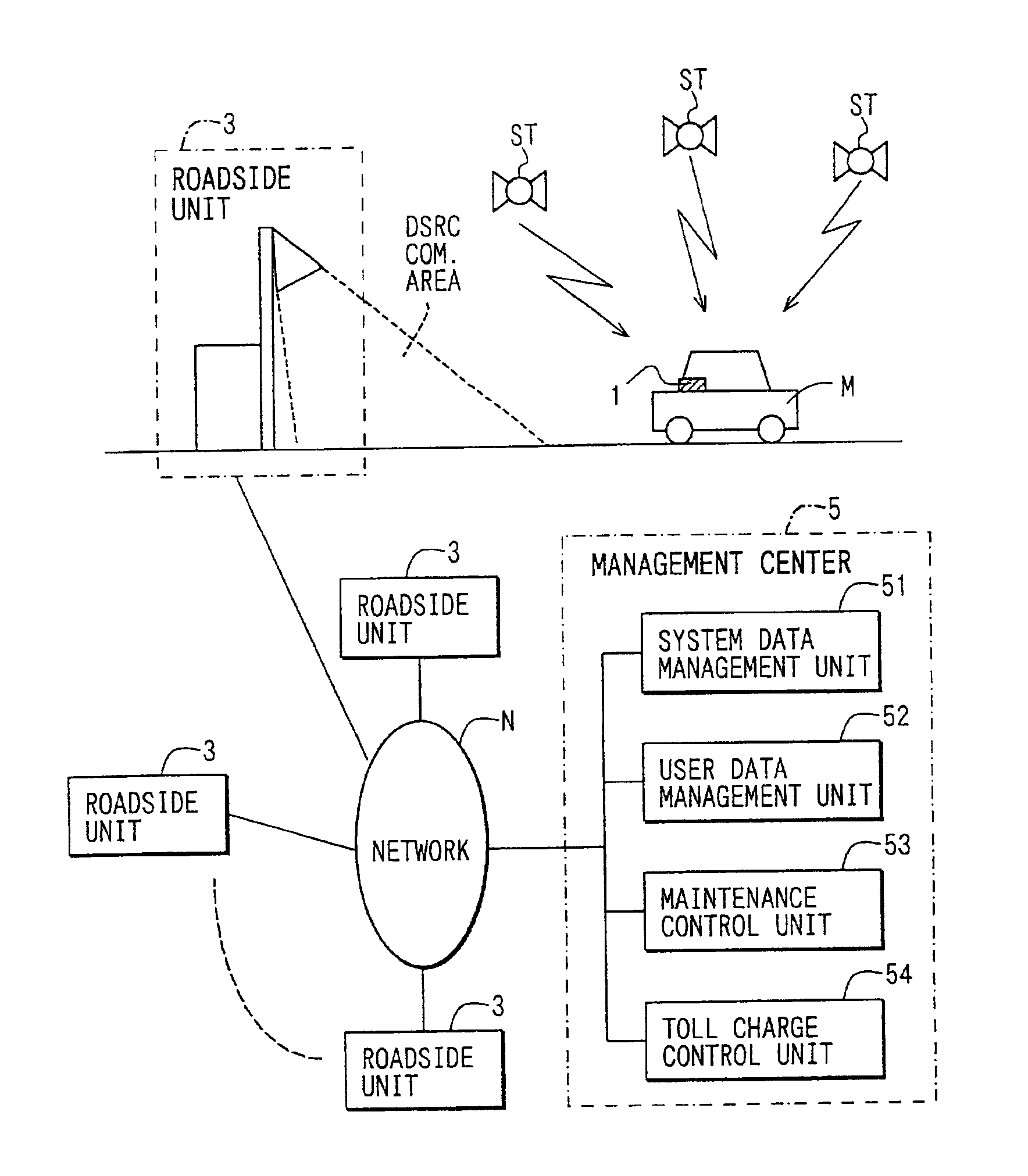
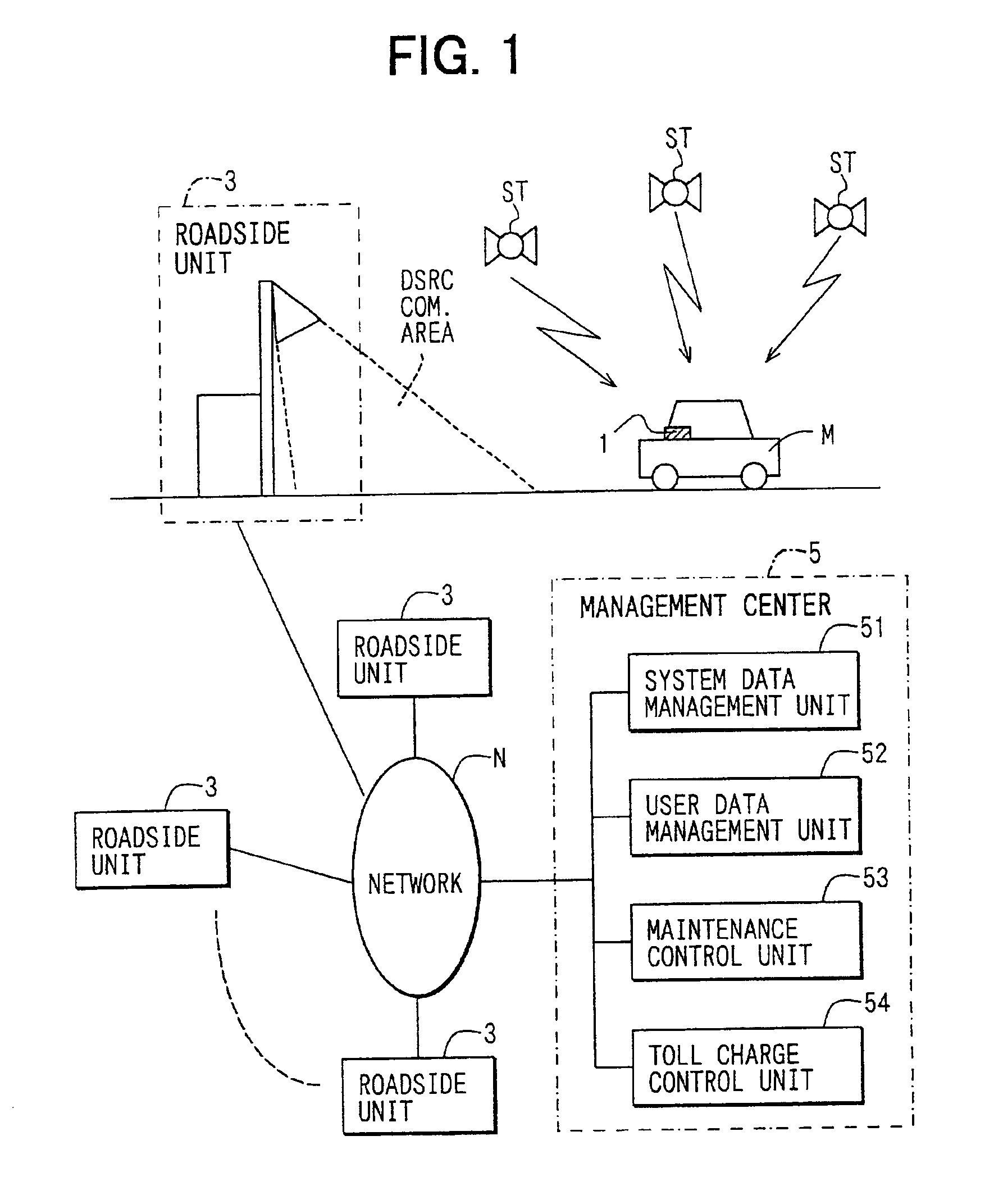
[0031]As is illustrated in FIG. 1, an automatic toll charging system (or a service providing system) according to a first embodiment of the present invention includes an in-vehicle apparatus 1, a plurality of roadside unites 3 and a management center 5. The in-vehicle apparatus 1 is installed in a vehicle M and determines a current position of the vehicle M upon receiving a radio signal indicative of the current position of the vehicle from a GPS satellite ST. Each roadside unit 3 communicates with the in-vehicle apparatus 1. The management center 5 acts as a management apparatus of the present invention communicated with each roadside unit 3 via a communication network N.

[0032]Each roadside unit 3 communicates with the in-vehicle apparatus 1 through a well known DSRC radio system having a short communication range of about 3 to 30 m (hereinafter, this communication is referred to as “road-vehicle communication”). Each roadside unit 3 is installed as a part of an E...

second embodiment

(Second Embodiment)

[0119]Next, a second embodiment of the present invention will be explained with reference to FIG. 10.

[0120]The second embodiment is similar to the first embodiment except few differences, so that only the differences will be described below.

[0121]As shown in FIG. 10, an in-vehicle apparatus 1a of the present embodiment only includes a main unit 10a, and a GPS receiver 11 is provided in place of the external device interface 25 of the main unit 10 of the first embodiment.

[0122]In this case, the “GPS OFF mode” of the first embodiment does not exist, so that an ERP process of the second embodiment is similar to that of the first embodiment except that steps S520, S530 and S580-S620 are omitted from the ERP process. Thus, in the second embodiment, functions and advantages similar to those of the first embodiment can be achieved.

[0123]In the second embodiment, although the GPS receiver 11 is provided in place of the external interface 25, it is possible to provide the ...

third embodiment

(Third Embodiment)

[0124]A third embodiment of the present invention will be explained with reference to FIG. 11.

[0125]The third embodiment is similar to the first embodiment except few differences, so that only the differences will be described below.

[0126]An in-vehicle apparatus 1b of the present embodiment only includes a main unit 10b. The main unit 10b of the third embodiment is similar to the position detection unit 20 of the first embodiment except that the main unit 10b further includes a display unit 14. The cellular phone 40 is connected to the external device interface 21.

[0127]Thus, in the in-vehicle apparatus 1b of the third embodiment, the communication (download and update of the system data, transmission of the toll charging data and the monitor data) is performed through the cellular phone 40.

[0128]In this case, since the user to be charged can be identified with a telephone number of the cellular phone 40, it is also possible to bill and collect the toll along with ...


PUM


Abstract

If acquisition of measured position and time data (position/time) from a position detection unit fails, a “GPS OFF mode” is set, and the latest position and time data is stored as start data. Thereafter, when the position and time data is obtained successfully, and the operation is recovered from the “GPS OFF mode”, the “GPS OFF mode” is cancelled. Also, the obtained position and time data (restoration data) is stored. Monitor data is formed from the start data and the restoration data. The monitor data is transmitted to a management center through road-vehicle communication. Also, history data of the position and time stored in the position detection unit during the “GPS OFF mode” is read. If the history data satisfies the toll charging condition, the toll charging data is formed and is transmitted to the management center.

Description

CROSS REFERENCE TO RELATED APPLICATION[0001]This application is based on and incorporates herein by reference Japanese Patent Application No. 2000-279905 filed on Sep. 14, 2000.BACKGROUND OF THE INVENTION[0002]1. Field of the Invention[0003]The present invention relates to an in-vehicle apparatus for executing a toll charging process when a current state of a vehicle (a current position, residence time or the like of the vehicle) satisfies a predetermined toll charging condition. The present invention also relates to a service providing system for providing a particular service through the in-vehicle apparatus.[0004]2. Description of Related Art[0005]To eliminate or reduce a traffic jam at a tollgate of a toll road, an ETC (Electronic Toll Collection) system and an ERP (Electronic Road Pricing) system have been proposed. The ETC system collects a toll without requiring the vehicle to stop at the tollgate. The ERP system collects the toll from a vehicle that enters a particular area ...

Claims


Application Information

Patent Timeline
Patent Type & Authority Patents(United States)
IPC IPC(8): G05D1/02G07B15/00G07C5/00G08G1/123G06Q10/00G06Q30/04G06Q30/06G06Q50/00G06Q50/26G08G1/13
CPCG07B15/063G07C5/008G08G1/205G07B15/00
Inventor TOKITSU, NAOKIYOSHIDA, ICHIRO
Owner DENSO CORP
Why Eureka
Try Eureka