Vehicle device and service supply system

A vehicle-mounted device and detection device technology, which is applied in the traffic control system of road vehicles, traffic control system, vehicle position indication, etc., can solve the problem of intentionally cutting off the signal line connected to the GPS receiver or intentionally cutting off the signal line connected to the GPS receiver. The power supply connected to the device, it is impossible to determine whether the vehicle meets the charging conditions, etc.

Inactive Publication Date: 2002-04-03
DENSO CORP
View PDF0 Cites 9 Cited by
  • Summary
  • Abstract
  • Description
  • Claims
  • Application Information

AI Technical Summary

Problems solved by technology

[0006] However, it is possible to perform various illegal operations on these in-vehicle devices
For example, if an IC card is used to identify a target (such as a vehicle) to be charged, someone may intentionally remove the IC card from the IC card reader connected to the vehicle-mounted device.
In addition, in the case of charging operations based on GPS receiver location measurements, someone may intentionally cut the signal line connected to the GPS receiver or may intentionally cut off the power supply connected to the GPS receiver
These actions make it impossible for the on-board device to determine whether the vehicle meets the charging conditions

Method used


Image

  • Vehicle device and service supply system
  • Vehicle device and service supply system
  • Vehicle device and service supply system

Examples


no. 1 example

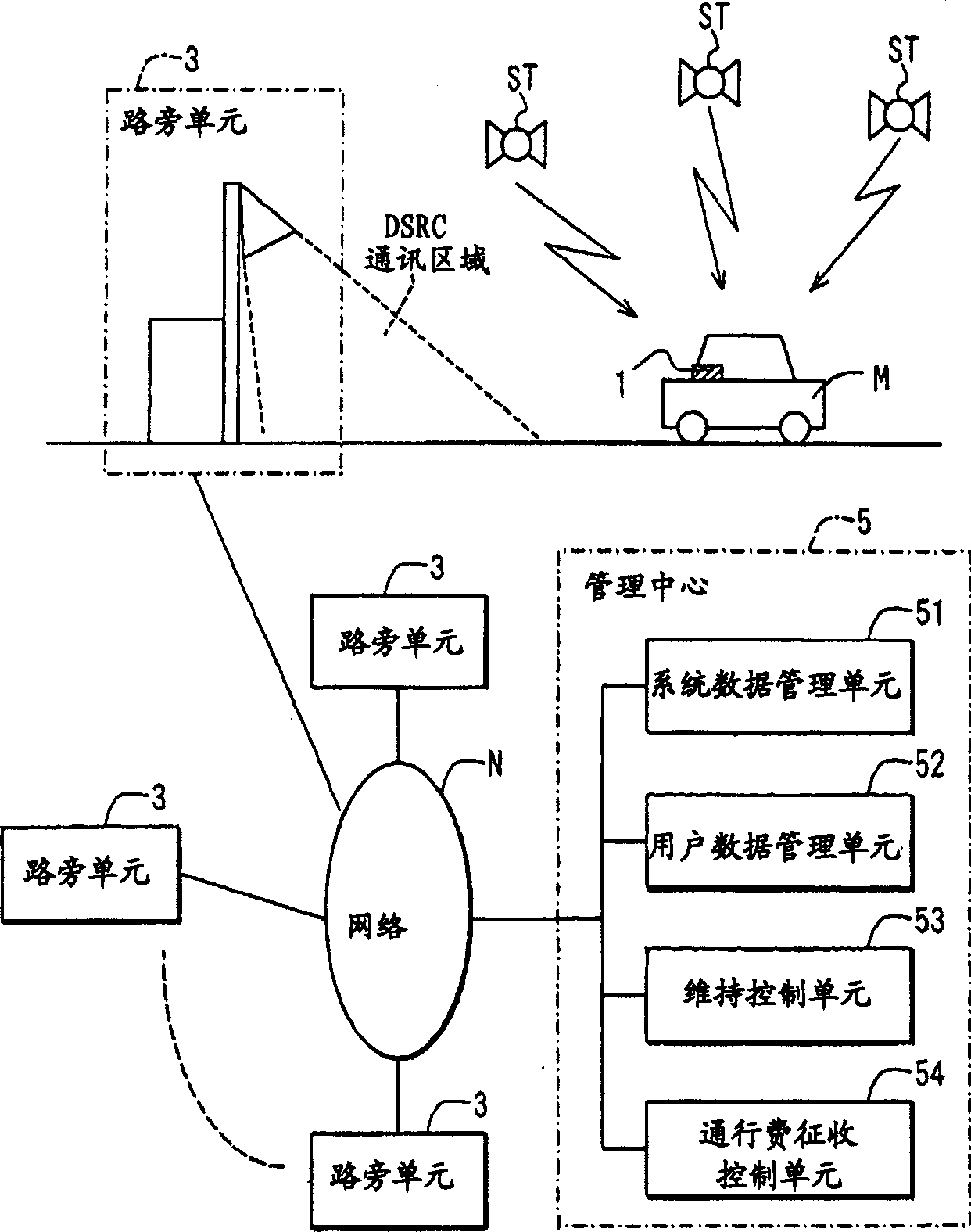
[0029] Such as figure 1 As shown, the automatic toll collection system (or service providing system) according to the first embodiment of the present invention includes an on-vehicle device 1 , a plurality of roadside units 3 and a management center 5 . The in-vehicle device 1 is installed in the vehicle M, and determines the current position of the vehicle M by receiving a radio signal indicating the current position of the vehicle from a GPS satellite ST. Each wayside unit 3 is in communication with the on-board device 1 . The management center 5, as the management device of the present invention, communicates with the roadside unit 3 through the communication network N.

[0030] Each wayside unit 3 communicates with the on-board unit 1 via the known DSRC radio system with a short communication range of about 3-30 m (this communication is hereinafter referred to as "road-to-vehicle communication"). Each roadside unit 3 is installed at a corresponding toll station of a toll...

no. 2 example

[0118] In the next step, the example will refer to Figure 10 The second embodiment of the present invention will be described.

[0119] Apart from a few differences, the second embodiment is similar to the first embodiment so only these differences are described below.

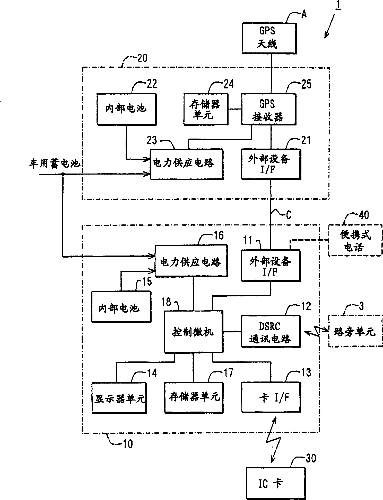
[0120] Such as Figure 10 As shown, the vehicle-mounted device 1a of the present embodiment includes only the main unit 10a, and a GPS receiver 11 is provided instead of the external device interface 25 of the main unit 10 of the first embodiment.

[0121] In this case, there is no GPS off mode of the first embodiment, so the ERP process of the second embodiment is similar to that of the first embodiment, except that the ERP process omits steps S520, S530 and S580-S620 . Therefore, in the second embodiment, functions and advantages similar to those of the first embodiment can be obtained.

[0122] In the second embodiment, although the GPS receiver 11 is provided instead of the external device interface 2...

no. 3 example

[0124] A third embodiment of the present invention will be described with reference to Reference 11.

[0125] Apart from a few differences, the third embodiment is similar to the first embodiment so only these differences are described below.

[0126] The vehicle-mounted device 1b of this embodiment includes only the main unit 10b. The main unit 10b of the third embodiment is similar to the position detection device 20 of the first embodiment except that the main unit 10b further includes a display 14 . Portable phone 40 is connected with external device interface 21

[0127] Therefore, in the vehicle-mounted device 1b of the third embodiment, communication (downloading and updating system data, transmission of toll collection data and monitoring data) is performed through the portable telephone 40 .

[0128] In this case, since the user to be charged can be identified by the telephone number of the portable phone 40, it is also possible to bill the toll and collect the toll...


PUM


Abstract

If acquisition of measured position and time data (position / time) from a position detection unit fails, a "GPS OFF mode" is set, and the latest position and time data is stored as start data. Thereafter, when the position and time data is obtained successfully, and the operation is recovered from the "GPS OFF mode", the "GPS OFF mode" is cancelled. Also, the obtained position and time data (restoration data) is stored. Monitor data is formed from the start data and the restoration data. The monitor data is transmitted to a management center through road-vehicle communication. Also, history data of the position and time stored in the position detection unit during the "GPS OFF mode" is read. If the history data satisfies the toll charging condition, the toll charging data is formed and is transmitted to the management center.

Description

field of invention [0001] The present invention relates to an on-vehicle device that executes a toll collection program when the current state of the vehicle (the vehicle's current position, residence time, or the like) satisfies a predetermined toll collection condition. The present invention also relates to a service providing system for providing a special service through an in-vehicle device. Background technique [0002] In order to eliminate or reduce traffic jams at road toll stations, ETC (Electronic Toll Collection) systems and ERP (Electronic Road Price Recording) systems have been proposed. ETC does not require vehicles to be parked at toll booths when collecting tolls. The ERP system charges tolls for vehicles entering a specific area (for example, an urban area) to reduce the traffic density in the area. [0003] In the ETC system, a DSRC (Dedicated Short Range Communication) radio system is used for road-vehicle communication between a roadside unit installed...

Claims


Application Information

Patent Timeline
Patent Type & Authority Applications(China)
IPC IPC(8): G05D1/02G06Q10/00G06Q30/04G06Q30/06G06Q50/00G06Q50/26G07B15/00G07C5/00G08G1/123G08G1/13
CPCG08G1/205G07C5/008G07B15/00G07B15/063
Inventor 时津直树吉田一郎
Owner DENSO CORP
Why Eureka
Try Eureka