Turntable for disk storage medium and disk drive including the turntable

Inactive Publication Date: 2005-08-30
PANASONIC CORP
View PDF21 Cites 1 Cited by
  • Summary
  • Abstract
  • Description
  • Claims
  • Application Information

AI Technical Summary

Benefits of technology

[0020]In order to overcome the problems described above, an object of the present invention is to provide a turntable that does not tilt when the shaft of a motor is inserted into the center hole

Problems solved by technology

Normally, unless the temperature of a product that has been molded out of a resin or metal with a die changes uniformly everywhere, the material of the molded product will shrink non-uniform

Method used


Image

  • Turntable for disk storage medium and disk drive including the turntable
  • Turntable for disk storage medium and disk drive including the turntable
  • Turntable for disk storage medium and disk drive including the turntable

Examples


embodiment 1

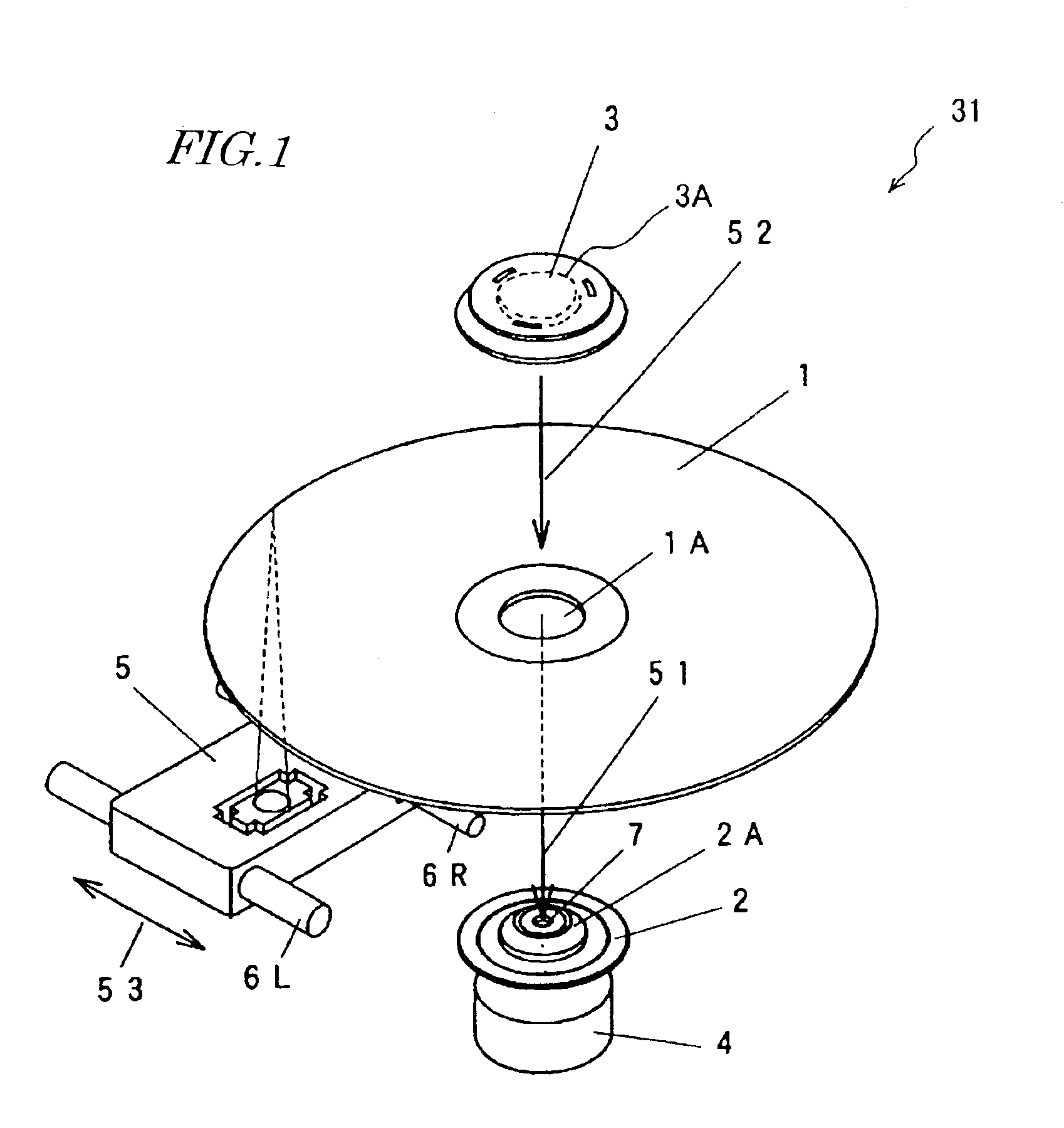
[0062]FIG. 1 schematically illustrates a first specific preferred embodiment of the turntable and disk drive according to the present invention.

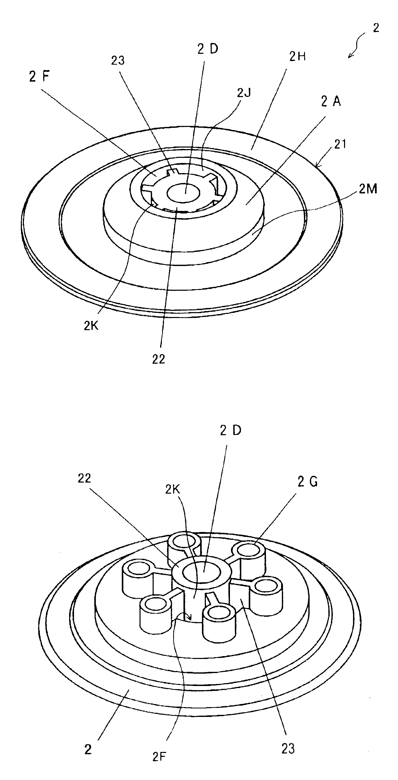
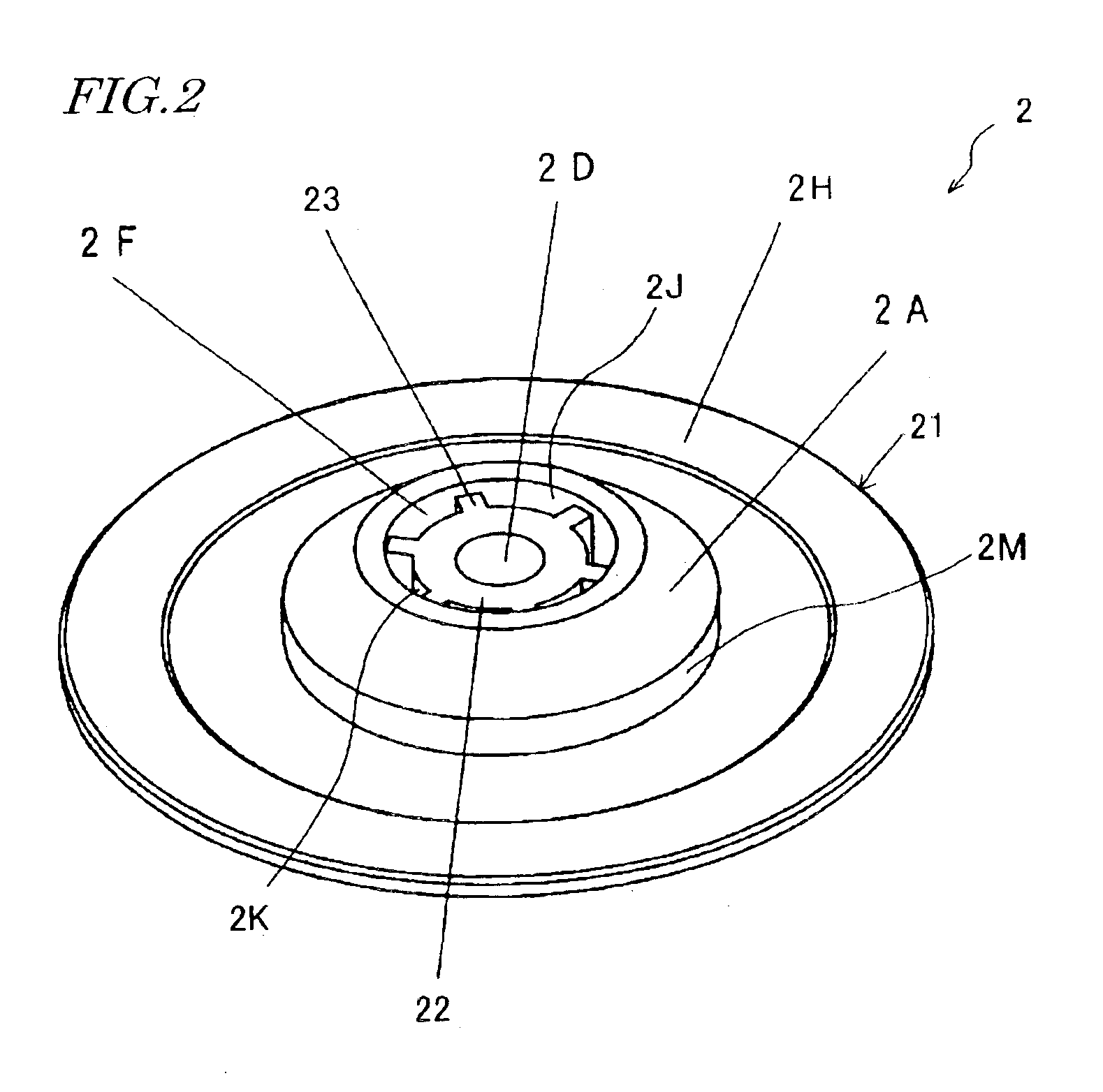
[0063]As shown in FIG. 1, the disk drive 31 includes turntable 2, motor 4 as a drive source for rotating the turntable 2, read / write head 5 for optically reading or writing information from / on a disk 1, and clamper 3 for securing and supporting the disk 1 onto the turntable 2.

[0064]The turntable 2 includes a center boss 2A, which is to be inserted into the center hole 1A of the disk 1 when the disk 1 is mounted thereon and on which a yoke 7 made of a magnetic material has been embedded. In this preferred embodiment, the turntable 2 is directly fitted with the rotating shaft (not shown) of the motor 4.

[0065]However, the turntable 2 does not have to be directly fitted with the rotating shaft of the motor 4. Alternatively, the motor 4 may also be connected to a rotating mechanism for transmitting the driving force of the motor 4 by way of gears...

embodiment 2

[0095]The disk drive 31 of the first specific preferred embodiment of the present invention described above uses the clamper 3 and the yoke 7 to fix the disk 1 on the turntable 2. On the other hand, in a disk drive 32 according to a second specific preferred embodiment of the present invention, the turntable itself includes a mechanism for fixing the disk thereon. A similar mechanism for fixing a disk on a turntable is disclosed in Japanese Laid-Open Publication No. 8-335351, for example.

[0096]As shown in FIG. 10, when the disk 1 is moved downward as indicated by the arrow 55 and mounted on a turntable 42 of the disk drive 32 according to this preferred embodiment, three spherical bodies 8A, 8B and 8C, which are exposed through the outer side face 42M of a center boss 42A and which constitute part of a force-applying mechanism, forces the disk 1 onto a disk mount surface 42H and thereby fixes it on the turntable 42.

[0097]The structure of this turntable 42 will be described in detail...


PUM


Abstract

A turntable for a disk storage medium includes disk mounting section, shaft center boss and ribs. The disk mounting section includes disk mount surface, center boss and inner side surface. The disk mount surface is used to mount the disk medium thereon. The center boss has an outer side face that engages with a center hole of the disk medium. The inner side face defines a space that has a center axis aligned with that of the center boss. The shaft center boss includes an outer side face and a hole into which a rotating shaft is inserted so as to transmit a driving force to, and rotate, the disk medium. The ribs join the outer side face of the shaft center boss and the inner side face of the disk mounting section together so that through holes are formed between these side faces.

Description

BACKGROUND OF THE INVENTION[0001]1. Field of the Invention[0002]The present invention relates to a turntable for a disk storage medium and a disk drive including the turntable.[0003]2. Description of the Related Art[0004]Apparatuses for reading or writing digital information optically and / or magnetically from / on a removable disk storage medium have been getting more and more popularized.[0005]FIG. 14 schematically illustrates a configuration for a disk drive 100 as an example of such apparatuses. The disk drive 100 shown in FIG. 14 is for use to optically read and write information from / on a disk 101. As shown in FIG. 14, the disk drive 100 includes turntable 102, motor 104 as a drive source for spinning the turntable 102, read / write head 105 for reading or writing information from / on the disk 101, and clamper 103 for securing and supporting the disk 101 onto the turntable 102.[0006]The turntable 102 includes a center boss 102A, which is to be inserted into the center hole 101A of t...

Claims


Application Information

Patent Timeline
IPC IPC(8): G11B17/028
CPCG11B17/0282
Inventor EZAWA, KOZOWAKIKAWA, MASANAOTERAMAE, KAZUOTATSUMI, TERUMI
Owner PANASONIC CORP
Why Eureka
Try Eureka