Quick position clamp and vise

a clamping and clamping technology, applied in the field of clamping systems, can solve the problems of limited teaching in the available positioning of the jaw, the overall strength of the system provided by the means of connection, and the available adjustment of the system and the control of the pieces, so as to enhance the positioning of the rod and the collar engagement. the effect of strengthening the connection

Inactive Publication Date: 2005-09-06
THE CLAMP
View PDF20 Cites 9 Cited by
  • Summary
  • Abstract
  • Description
  • Claims
  • Application Information

AI Technical Summary

Benefits of technology

[0007]The present invention provides an improved tension rod positioning apparatus and method for C-type clamps and Vises. The present invention uses at least three teeth on a toothed rod inserted into a toothed hole on an engagement collar. When the rod and hole are aligned, the rod may be freely positioned within the collar. When the rod is inserted into the collar, the three teeth center the rod within the collar to provide an axial alignment ...

Problems solved by technology

As can be noted by the disclosure of this patent, this teaching is limited in the available positioning of the jaws by the engagement of the teeth.
These prior art patents have several disadvantages i...

Method used


Image

  • Quick position clamp and vise
  • Quick position clamp and vise
  • Quick position clamp and vise

Examples


Embodiment Construction

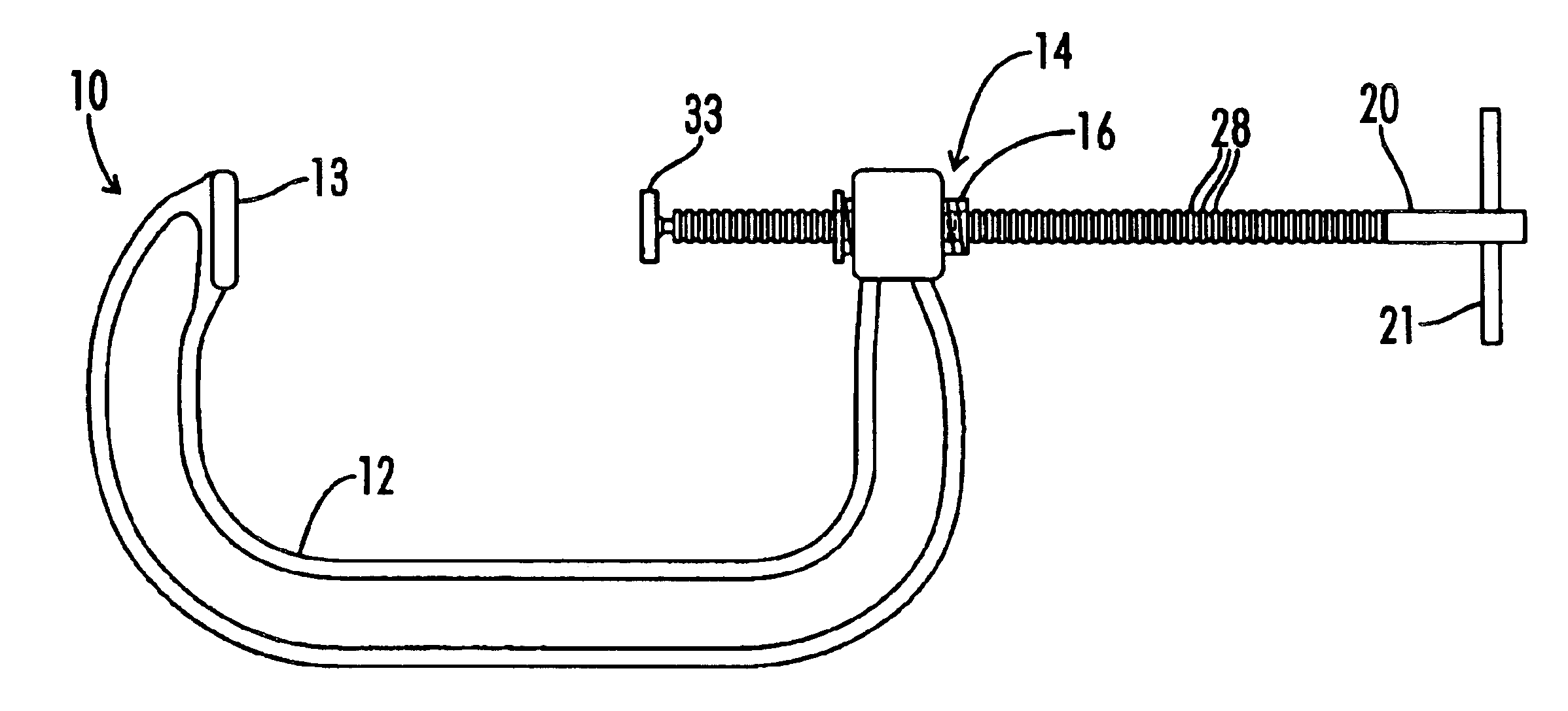
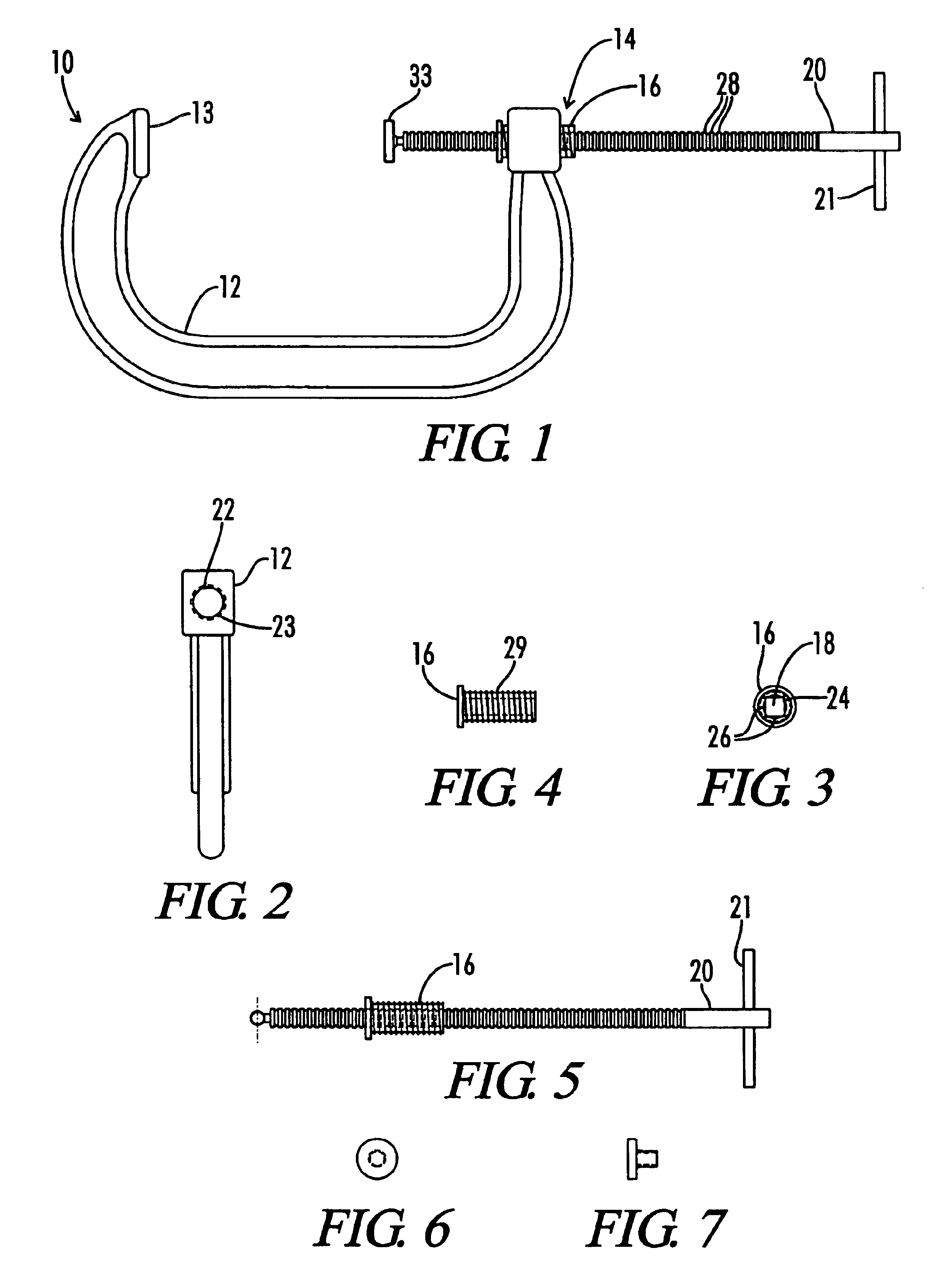
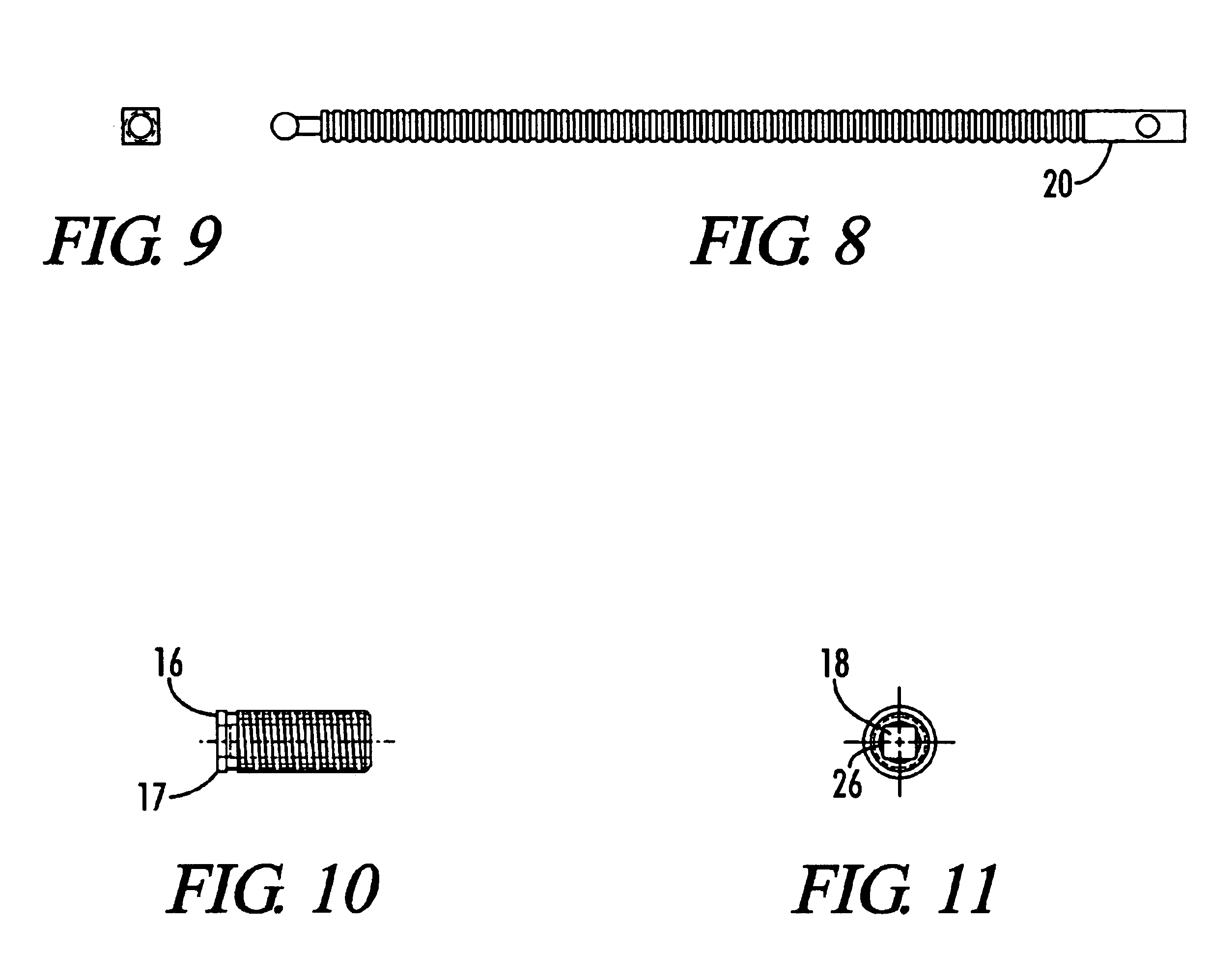
[0021]FIGS. 1 through 32 show the quick position C-type clamp 10 of the present invention. The opening and closing of the quick position C clamp 10 is a slide and final screw motion instead of the basic all screw method as taught in the prior art. The quick position “C” Clamp 10 is a time saving, labor saving tool. To open a conventional 6″“C” clamp requires approximately 1 to 2 minutes. To open and close the Quick position “C” Clamp 10 requires approximately 2 seconds. The arrangement of the present invention also provides advantages over previous attempts of the prior art methods for C clamps.

[0022]As shown in FIG. 1, the U-shaped or “C” clamp frame shown as the body 12 is manufactured of cast steel that is used to hold the pressure applied by the handle 21 through the threaded bar 20, also known as a rod 20 to the bearing pad 13. The sliding action consists of a bar lock assembly unit 14 shown in detail in FIGS. 3 through 11 that includes a square threaded bar 20 passing through ...


PUM


Abstract

A tension rod positioning apparatus and method for C-type clamps and Vises including a shaped threaded rod inserted into a shaped threaded hole on an engagement collar. When the shaped rod and shaped hole are aligned, the rod may be freely positioned within the collar. When the shaped rod is inserted into the collar and turned, the rod engages and turns the engagement collar. The engagement collar includes an external thread sized to fit an internal thread on a clamp base. In this manner, the rod may be inserted and then turned in one direction to both engage the engagement collar and increase the clamping pressure. After clamping, the shaped rod may be turned in the opposite direction to loosen the clamping pressure and disengage the engagement collar. Once the rod and collar have been disengaged by aligning the shaped rod and shaped hole of the engagement collar, the length of the rod may be freely moved within the engagement collar to reposition the clamp for the next operation.

Description

[0001]This application claims benefit as a continuation application of U.S. patent application Ser. No. 10 / 154,421 filed May 23, 2002 now U.S. Pat. No. 6,726,193, entitled “Quick Position Clamp and Vise”, which claims priority to provisional U.S. patent application Ser. No. 60 / 292,999 filed May 23, 2001, entitled “Quick Position Clamp and Vise” both of which are hereby incorporated by reference in their entirety.BACKGROUND OF THE INVENTION[0002]The present invention relates generally to clamping systems and more specifically, this invention relates to c-clamps and vises and provides an improved quick position method and apparatus for use of these devices.[0003]Several U.S. patents describe clamping systems. These include: U.S. Pat. No. 298,704 issued to Norris et al. on May 13, 1884; U.S. Pat. No. 823,748 issued to Walden on Jun. 19, 1906; U.S. Pat. No. 825,151 issued on McLean on Jul. 3, 1906; U.S. Pat. No. 947,619 issued to Orr on Jan. 25, 1910; U.S. Pat. No. 1,140,646 issued to A...

Claims


Application Information

Patent Timeline
IPC IPC(8): B25B1/12B25B1/00B25B5/00B25B5/10
CPCB25B1/125B25B5/10B25B5/101
Inventor YATES, HOWARD PRESTON
Owner THE CLAMP
Why Eureka
Try Eureka