Energy absorbing front frame structure for a vehicle

a front frame and energy-absorbing technology, applied in the direction of roofs, transportation and packaging, vehicle arrangements, etc., can solve the problems of limited amount and duration of compression that can be achieved for a given vehicl

Active Publication Date: 2005-09-06
FCA US
View PDF15 Cites 61 Cited by
  • Summary
  • Abstract
  • Description
  • Claims
  • Application Information

AI Technical Summary

Benefits of technology

[0009]The combined actions of the various sections and selectively crushable junctures of the front frame structure of the invention allow for a higher percentage of the length of the portion of the vehicle extending forward from the passenger compartment to be compressed, during a frontal collision, than is achievable with prior energy-absorbing front frame structures. Depending upon the vehicle, a front frame according to the invention can add 5 to 10 inches of additional compressible length, as compared to the same vehicle using prior energy absorbing front frame structures. The various sections and selectively crushable junctures of the front frame structure of the invention are also predisposed to move, during the collision, in directions and to locations that provide additional protection to occupants of the vehicle. The duration of energy absorption is also increased, thereby allowing more time for supplemental restraint systems to be deployed, and lowering G-forces exerted on the occupants, during the collision. Depending upon the vehicle, a front frame structure according to the invention can increase the duration of compression by as much as fifty percent, as compared to the same vehicle using a prior energy absorbing front frame structure.

Problems solved by technology

The amount and duration of compression that can be accomplished for a given vehicle are limited, of course, by the size and shape of the vehicle, and in particular by the percentage that the length of the portion of the vehicle extending forward from the passenger compartment can be compressed during the collision.

Method used


Image

  • Energy absorbing front frame structure for a vehicle
  • Energy absorbing front frame structure for a vehicle
  • Energy absorbing front frame structure for a vehicle

Examples


Embodiment Construction

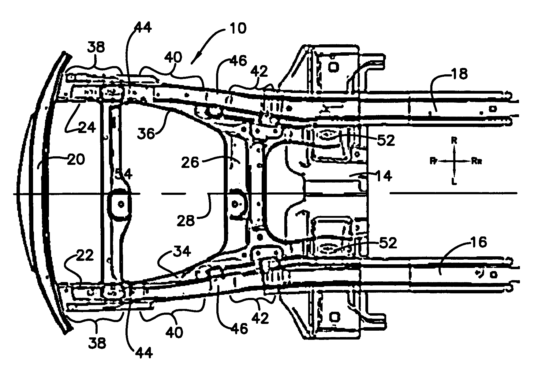
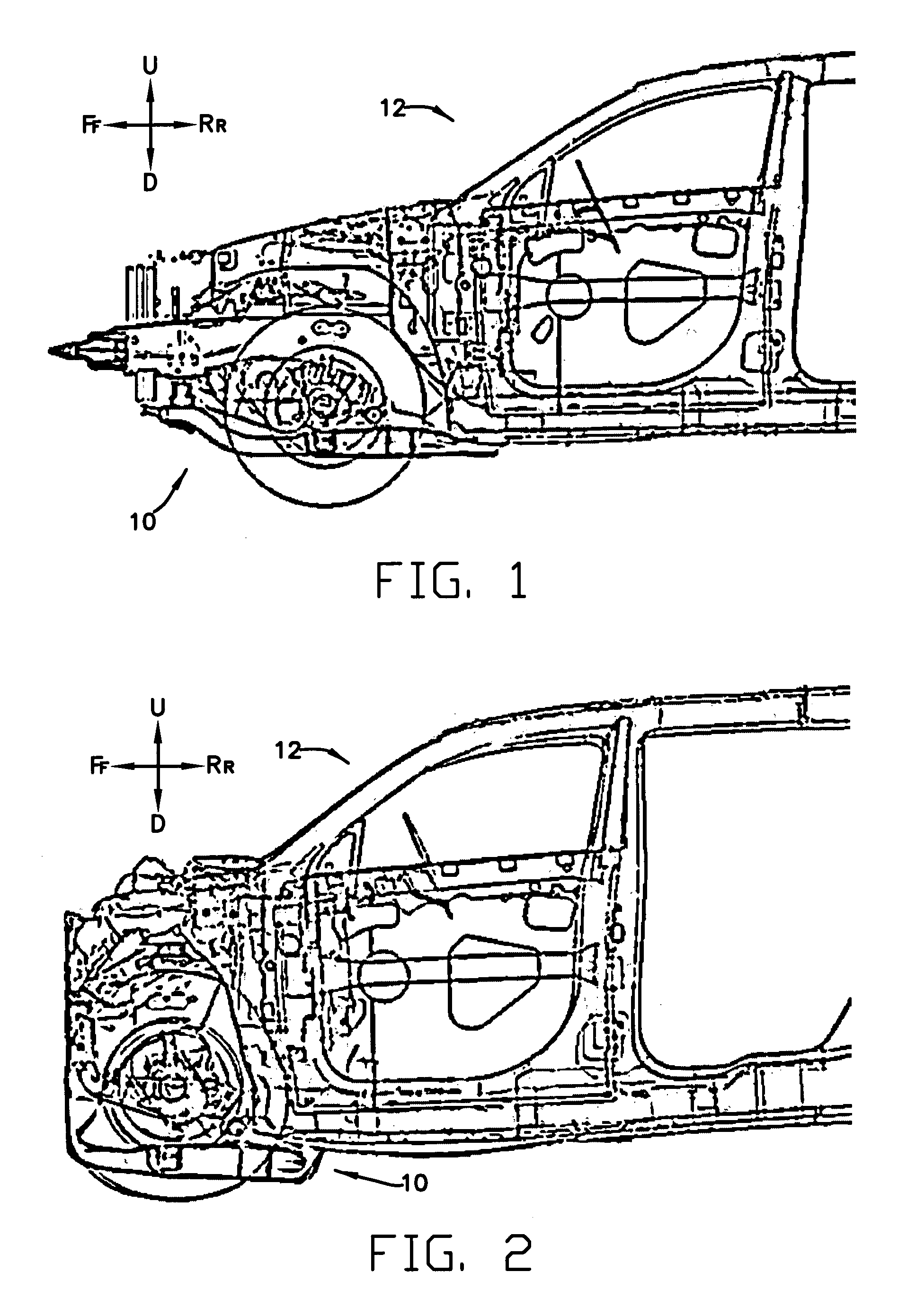
[0028]FIGS. 1–7 show an exemplary embodiment of a front frame structure 10, for absorbing energy during a frontal collision of a vehicle 12. FIGS. 1 and 2, respectively, show the vehicle 12 and the front frame structure before and after a frontal collision of the vehicle with a solid barrier extending completely across the front end of the vehicle 12 in a direction that is perpendicular to a longitudinal axis of the vehicle 12.

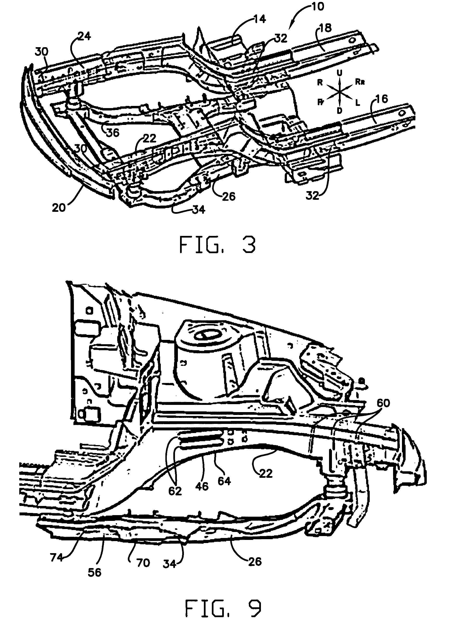
[0029]For clarity of illustration, the majority of the vehicle 12 is not shown in FIGS. 3–7. FIGS. 3–5 show the front frame structure 10 before the collision, together with only a floor pan 14, and a pair of left and right side rails 16, 18 of the remainder of the vehicle 12. FIGS. 6 and 7 show the front frame structure 10, the floor pan 14, and the side rails 16, 18 after the collision.

[0030]Because the invention includes components that are moved, deformed and / or crushed during the collision in a manner that alters their appearance and location, the reader m...


PUM


Abstract

A method and apparatus for absorbing energy during a frontal collision of a vehicle, through the use of a front frame structure having main frame rails that include several deformable and non-deformable sections which are connected by selectively crushable junctures that are configured to predispose one or more of the junctures and sections to pivot selectively outward, rearward and upward, in a predetermined manner, during the collision. The front frame structure also includes an engine cradle, attached below the main frame rails, and having a pair of side rails that include forward and rear crushable junctures joined by non-deformable intermediate sections, with the crushable junctures of the main frame rails and engine cradle side rails being configured to predispose the intermediate sections of the engine cradle side rails to move downward and rearward during the collision.

Description

TECHNICAL FIELD OF THE INVENTION[0001]This invention relates to chassis structures for motor vehicles, and more particularly to absorbing energy in a front frame structure of such a chassis during a frontal collision of the vehicle.BACKGROUND OF THE INVENTION[0002]It is generally known that it is advantageous to configure a motor vehicle such that a forward section of the vehicle will be predisposed to deform in a predetermined manner during a frontal collision, to thereby provide protection to occupants of the vehicle. Various governmental and industry organizations, such as the National Highway Safety and Transportation Authority (NHTSA) and the Insurance Institute for Highway Safety (IIHS) have promulgated standardized testing procedures, standards, and rating systems relating to the performance of vehicles during frontal collisions.[0003]There are several aspects to providing acceptable protection of the occupants. It is desirable to cause the components of the forward part of t...

Claims


Application Information

Patent Timeline
Patent Type & Authority Patents(United States)
IPC IPC(8): B60J7/00B60R27/00B60R99/00B62D21/15
CPCB62D21/152B62D21/155
Inventor CORNELL, TROY MBURKE, GERALD FGU, HARRYNAICK, PRATAPKIRSCHMANN, MARKBEECHER, GREGORY AGILL, HARJEETSHIPP, ERINHALLER, KENNETH JOKUNIEWICZ, MICHAELSTAISCH, MANFREDCOTTRELL, DAVEOSOSKI, LARRYHARTMANN, NORMAN
Owner FCA US
Why Eureka
Try Eureka