Compact work light with high illumination uniformity

a work light and uniform illumination technology, applied in the field of work lights, can solve the problems of large variation in light spilling out to a wide area, and high intensity of the circular spo

Inactive Publication Date: 2005-09-06
OPTICS 1
View PDF3 Cites 50 Cited by
  • Summary
  • Abstract
  • Description
  • Claims
  • Application Information

AI Technical Summary

Problems solved by technology

A significant problem with the current flashlight technology is that the crude image (usually a circular spot) varies significantly in its intensity.
While some flashlights permit the user to vary or adjust the size of the pattern, it is generally highly non-uniform in intensity over the spot.
Another problem is that the light spills out to a wide area outside of the intended spot area.
Another problem is that the crude image cast by a conventional flashlight makes it difficult in many circumstances to clearly see the object of interest.
Another problem is that the illuminated area of prior art flashlights tends to be unattractive and unfamiliar.
Unfortunately, conventional flashlights do not provide such illumination.
In the cases where such lights attempt to achieve even a modest amount of illumination uniformity, they are usually immense, cumbersome, unwieldy and / or inefficient.

Method used


Image

  • Compact work light with high illumination uniformity
  • Compact work light with high illumination uniformity
  • Compact work light with high illumination uniformity

Examples


Embodiment Construction

[0028]For the purposes of explanation, specific embodiments are set forth to provide a thorough understanding of the present invention. However, it will be understood by one skilled in the art, from reading the disclosure, that the invention may be practiced without these details. Moreover, well-known elements, process steps, and the like, and including, but not limited to, optical components, electronic circuitry components and connections, are not set forth in detail in order to avoid obscuring the disclosed system.

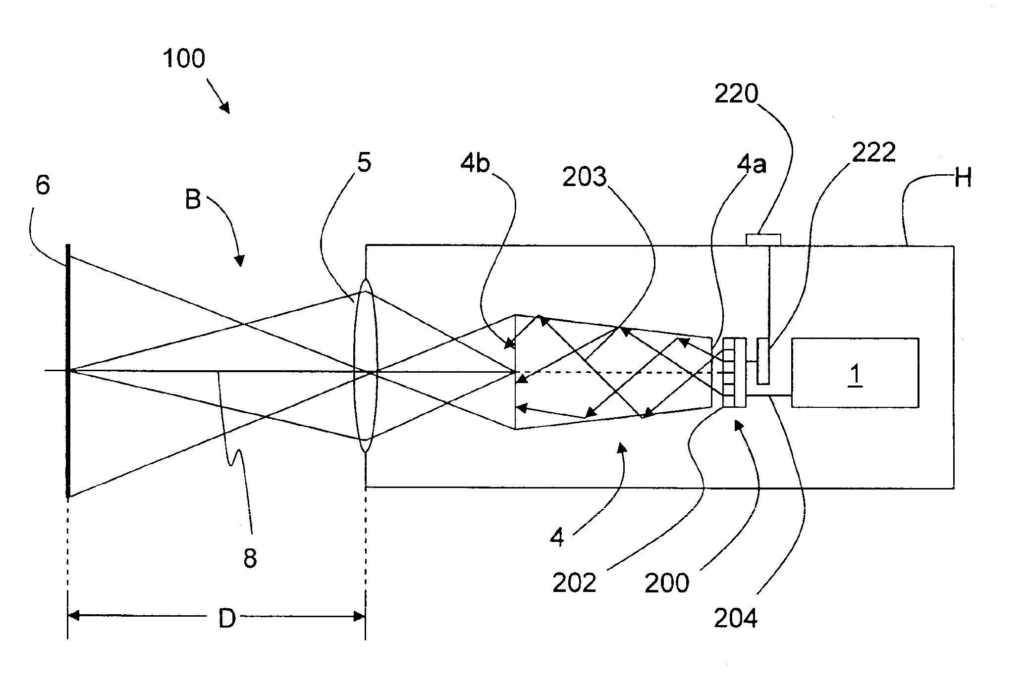
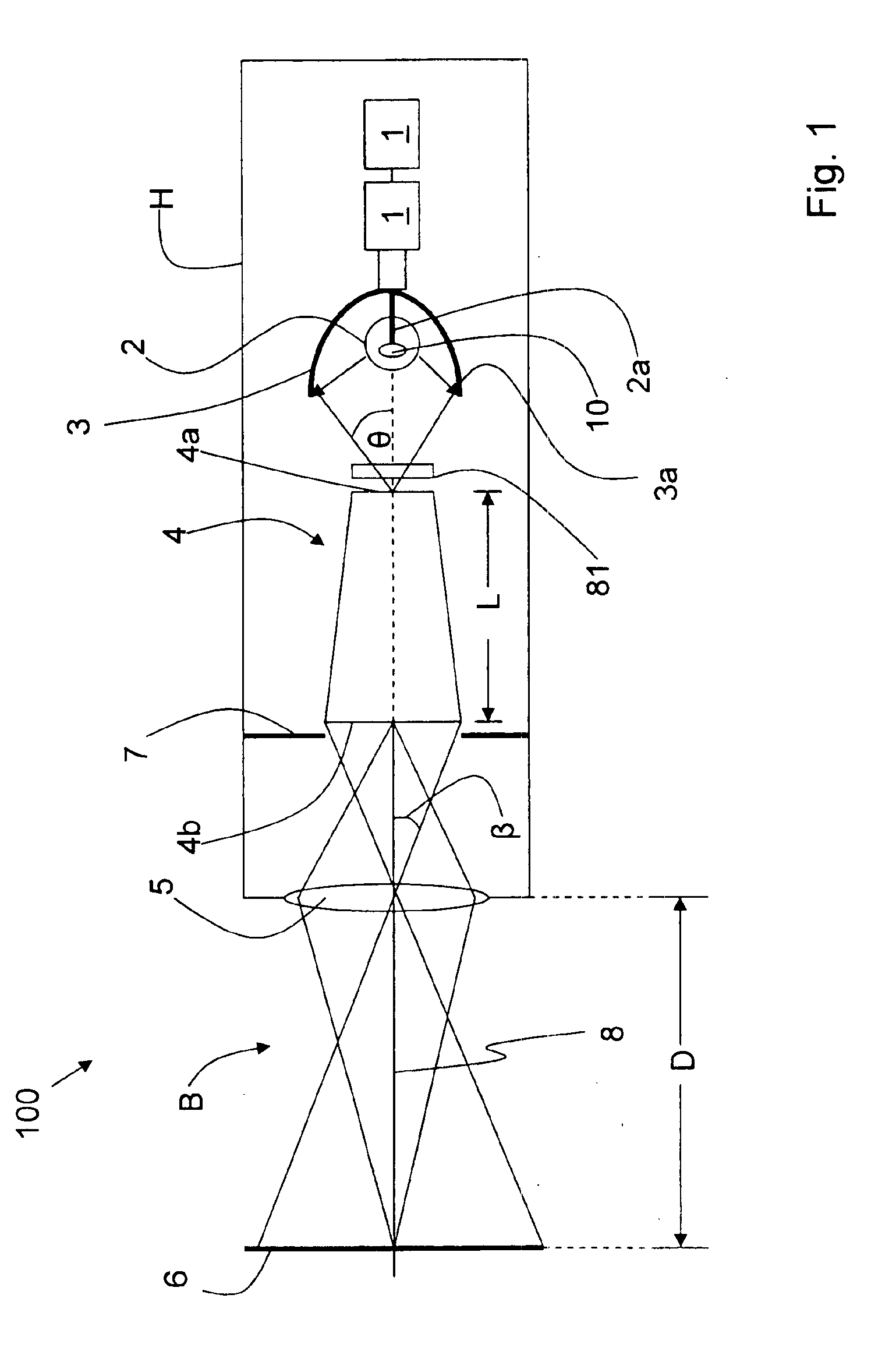
[0029]The preferred example embodiment of the flashlight invention 100 is shown in FIG. 1. Flashlight 100 includes a housing H which serves to enclose and / or support and protect (i.e., “house”) the various elements making up the flashlight as described below. Two ordinary flashlight batteries 1 are shown in flashlight 100 of FIG. 1, but any number of batteries (i.e., one or more), or types of batteries, or any applicable power source will work as a power source for a co...


PUM


Abstract

A compact work light that generates a light beam having high brightness and high illumination uniformity is disclosed. The work light includes a housing that houses a light source, a light homogenizer and an imaging lens in an operational relationship. The housing is attached to an adjustable mount, which can be attached to a fixed region such as wall, or to a movable support member such as a lamp base. The light source generates light that is uniformized by the light homogenizer. The homogenized light is then imaged by the imaging lens as a highly uniform, bright beam spot having a sharp boundary. The beam spot is formed at a selectable distance from the work light by varying the imaging lens and / or the adjustable mount. The work light is useful for a variety of industrial, professional and personal applications, including but not limited to a reading light, a dentist light, a head lamp, a head light and an optical projector.

Description

CROSS-REFERENCE TO RELATED APPLICATIONS[0001]This patent application is a continuation-in-part of U.S. patent application Ser. No. 10 / 794,073, filed Mar. 5, 2004, which is a continuation-in-part of U.S. patent application Ser. No. 10 / 068,366, filed Feb. 5, 2002, now U.S. Pat. No. 6,746,124, filed on Feb. 5, 2002, which in turn claims priority from U.S. Provisional Application No. 60 / 266,589, filed Feb. 6, 2001.BACKGROUND INFORMATION[0002]1. Field of the Invention[0003]This invention relates to work lights, and in particular to work lights having high brightness and a high degree of illumination uniformity.[0004]2. Description of the Related Art[0005]The flashlight was invented in 1898 by Conrad Hubert who turned a metal tube, a light bulb and a battery into the world's first flashlight. Little has changed in flashlight technology since then. Today's flashlight technology is based on locating a tungsten lamp or bulb at the focus of a parabolic reflector and simply imaging the filamen...

Claims


Application Information

Patent Timeline
Patent Type & Authority Patents(United States)
IPC IPC(8): G03B21/14
CPCF21V5/006F21Y2115/10G03B21/208
Inventor FISCHER, ROBERT E.GORTYCH, JOSEPH E.
Owner OPTICS 1
Why Eureka
Try Eureka