Fuel dispensing and containment assembly

a technology of containment assembly and fuel, which is applied in the direction of vehicle maintenance, functional valve types, liquid transfer devices, etc., can solve problems such as lack of appreciation

Inactive Publication Date: 2005-09-06
GROPP STEVEN M
View PDF23 Cites 12 Cited by
  • Summary
  • Abstract
  • Description
  • Claims
  • Application Information

AI Technical Summary

Benefits of technology

[0008]It is an object of the present invention to provide a modular fuel dispensing and containment assembly which utilizes a fuel tank held within a reinforced concrete vault which is located underground. In conjunction with the vault, a manifold of corridors is also located underground and leads to a plurality of dispensing modules. The interior of the corridors and dispensing modules form a single interconnected air volume and the tank and piping are all retained within liquid impermeable containment structures.
[0009]The present invention is for a modular fuel dispensing and containment system for storing fuel and at least one fuel tank and pumping the fuel to a plurality of fuel dispensers at locations remote from the fuel tank. The system has a reinforced vault located underground, which vault has a floor, side walls and a top supporting a lid. A fuel tank is held within the reinforced concrete vault and is separated from one or more of the w

Problems solved by technology

Years ago, there was a lack of appreciation of the negative consequences of

Method used


Image

  • Fuel dispensing and containment assembly
  • Fuel dispensing and containment assembly
  • Fuel dispensing and containment assembly

Examples


Embodiment Construction

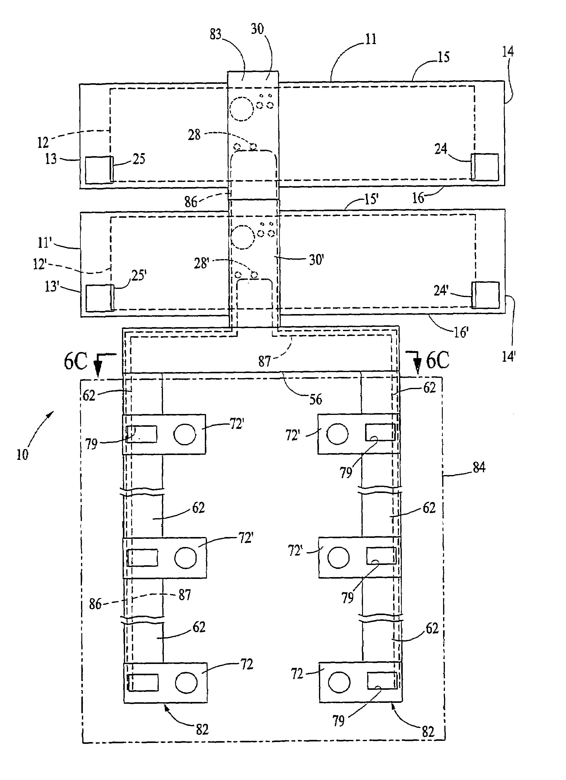
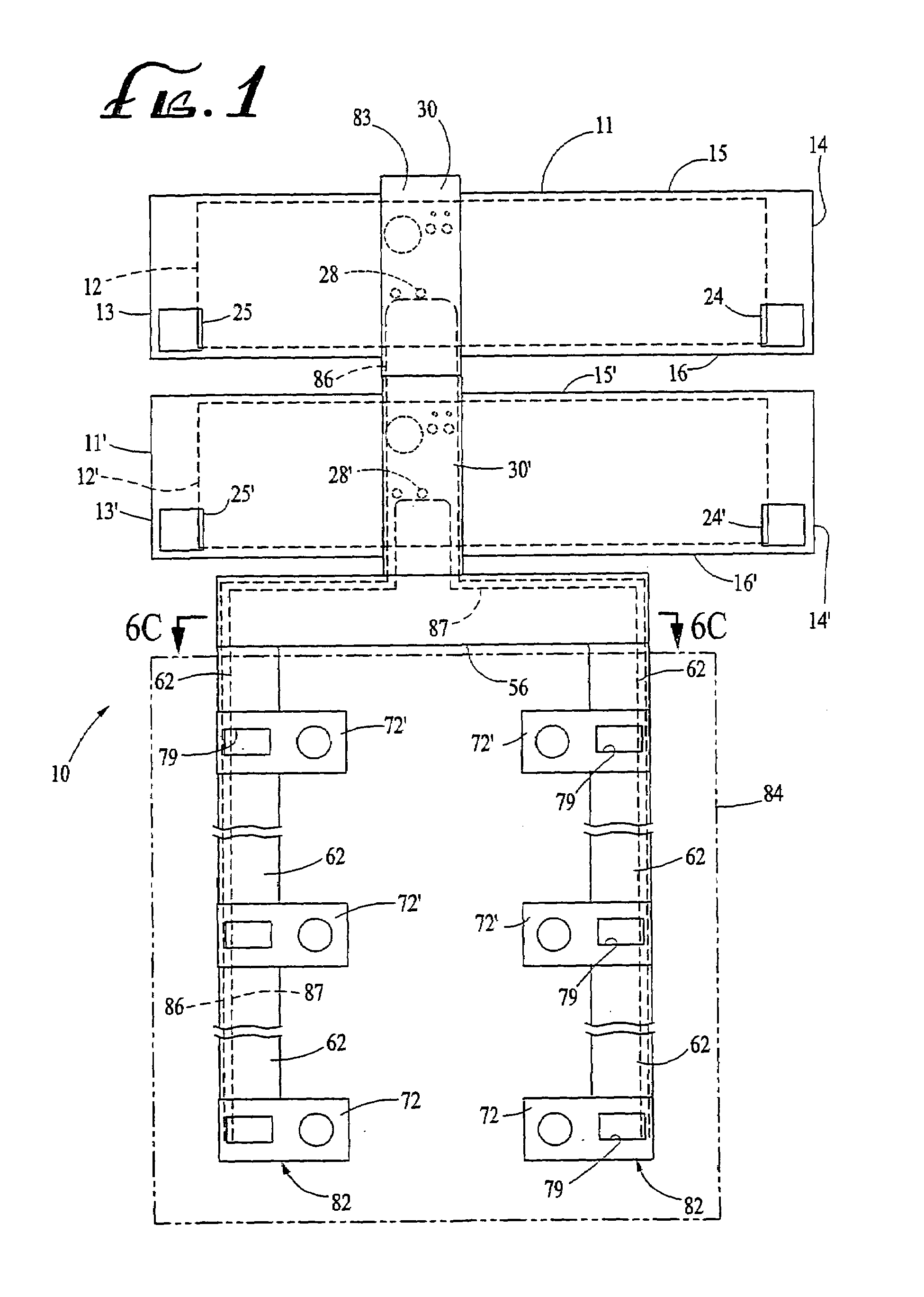
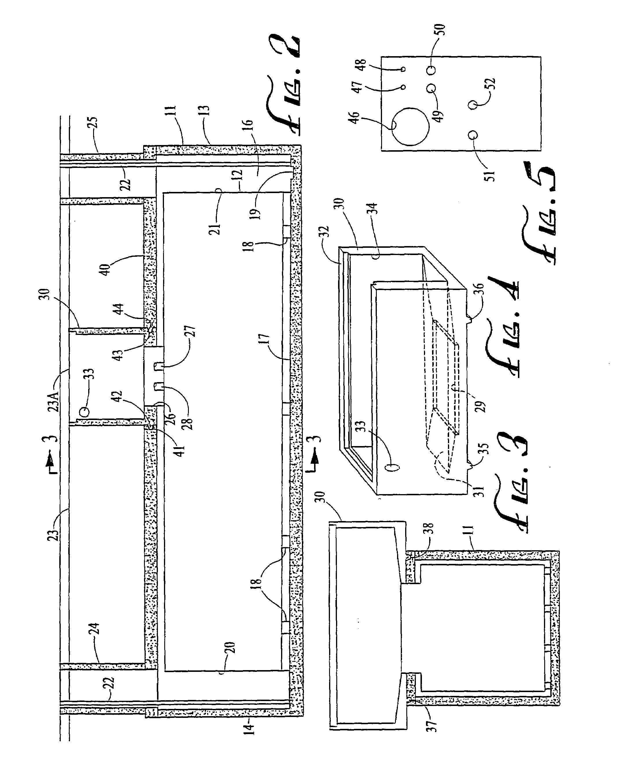
[0022]A plan diagrammatic view of the modular fuel dispensing and containment assembly of the present invention is shown in FIG. 1 and indicated generally by reference character 10. Assembly 10 has a first reinforced concrete vault 11 which contains a first fuel tank 12 shown in phantom view. Vault 11 has a first end wall 13, a second end wall 14, a first side wall 15, and a second side wall 16. As shown in FIG. 2, vault 11 has a floor 17 and fuel tank 12 is supported above floor 17 a distance, such as 4″, by a plurality of legs 18. Floor 17 is sloped toward a leak collection monitoring sump 19.

[0023]Tank 12 has a first end wall 20 and a second end wall 21. Both end walls are preferably spaced from their respective vault end walls a distance sufficient to permit service personnel to enter the vault and physically observe fuel tank 12. A 30″ spacing has been found sufficient for this purpose and separately installed ladder unit 22 is provided in the end walls to assist in the entry i...


PUM


Abstract

A modular fuel dispensing and containment assembly for storing fuel in at least one fuel tank and for pumping the fuel to a group of fuel dispensers. The assembly has a reinforced concrete vault located underground which contains a fuel tank within its interior. The fuel tank is separated from the interior walls of the vault. The fuel tank has a turbine corridor on its lid, which corridor has an interior volume which leads from the fuel tank to a series of piping corridors. The turbine corridor and the piping corridors are all underground and the piping corridors lead to dispensing modules which are located under the dispensers or gas pumps. The dispenser modules and piping corridors are all sufficiently large to permit the entry of service personnel to their interiors. The interiors of the various corridors and modules form a single interconnected air volume. The result is a fuel dispensing and containment assembly wherein the vault and corridors and dispensing modules act as a secondary containment against any contaminant leaking from the primary piping or tanks. It also permits complete visual inspection of the primary containment and physical access to all its parts at any time.

Description

CROSS REFERENCE TO RELATED APPLICATIONS[0001]This application is a continuation of applicant's application Ser. No. 10 / 078,575, filed Feb. 20, 2002, abandoned.BACKGROUND OF THE INVENTION[0002]The field of the invention is fuel dispensing and containment systems and the invention relates more particularly to systems which utilize a fuel tank which is held in an underground concrete vault. The vast majority of “gas stations” utilize fuel storage tanks which are buried directly underground. Years ago, there was a lack of appreciation of the negative consequences of fuel leaking from the underground tank and associated piping into the ground. With the present enlightened ecological sensitivity, vast amounts of money are spent to try to remove all fuel which might have leaked from such storage tanks and piping into the surrounding ground water table. Various funds have been established to help finance such cleanup procedures and a per-gallon charge is levied against dispensed fuel to cre...

Claims


Application Information

Patent Timeline
IPC IPC(8): A22C11/12A22C11/02A22C11/00B60S5/02B60S5/00B65D88/02B65D90/22B65D90/24B65D88/76B65D88/00B67D5/60B67D7/78
CPCB60S5/02B65D88/022B65D88/76B65D90/24B67D7/78Y10T137/5762
Inventor GROPP, STEVEN M.
Owner GROPP STEVEN M
Why Eureka
Try Eureka