Apparatus and method for connecting pipes during underwater pipe-laying

a technology of underwater pipe-laying and apparatus, which is applied in the direction of soldering apparatus, manufacturing tools,auxillary welding devices, etc., can solve the problems of increasing the time taken to complete the welding joint, the use of a pipe-in-pipe design complicating the welding process, and the addition of pipe sections

Inactive Publication Date: 2005-09-06
SAIPEM SPA
View PDF91 Cites 14 Cited by
  • Summary
  • Abstract
  • Description
  • Claims
  • Application Information

AI Technical Summary

Benefits of technology

[0020]Preferably the first axial part of the annular member includes a portion of reduced external diameter adjacent to the flange part, whereby, when the annular member is fitted in the end of the first outer pipe, an annular cavity is formed between the annular member and the inside of the end of the first outer pipe, the cavity being defined by the inside of the first outer pipe, the o

Problems solved by technology

A problem associated with J-laying is the means by which additional pipe sections are added to the pipeline.
Further problems are encountered when the pipeline in question uses what is commonly referred to as a “pipe-in-pipe” design.
The use of a pipe-in-pipe design complicates this welding process because the inner pipe must be welded before the outer pipe can be welded, so that two separate welding operations are required at one joint.
Thus the time taken to complete a welded joint becomes more critical.
A particular problem arises with welding of the ends of the outer pipe in a pipe-in-pipe design because those ends do not generally need to be prepar

Method used


Image

  • Apparatus and method for connecting pipes during underwater pipe-laying
  • Apparatus and method for connecting pipes during underwater pipe-laying
  • Apparatus and method for connecting pipes during underwater pipe-laying

Examples


Embodiment Construction

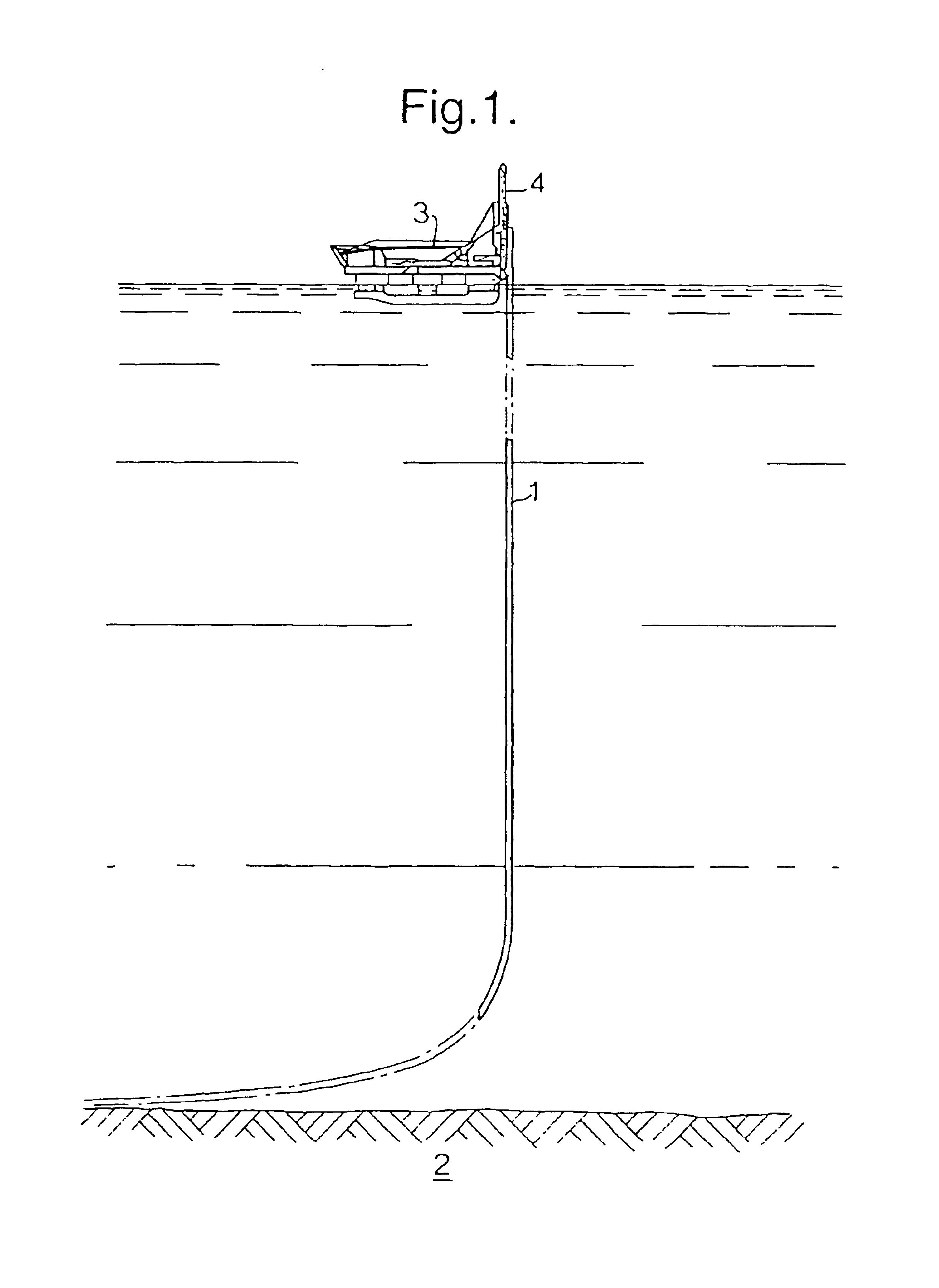
[0037]FIG. 1 shows a pipeline 1 being laid on a seabed 2 by a J-laying technique using a vessel 3. The vessel 3 has a tower 4, which is shown in FIG. 1 as vertical but may also be adjusted to an angle inclined to the vertical. The upper end of the pipeline 1 is supported by appropriate means of the tower 4 and is lowered down the tower as the pipeline is laid. Additional lengths of pipeline are welded to the upper end of the pipeline as it passes down the tower 4. In the example described, the pipeline 1 is of a pipe-in-pipe design.

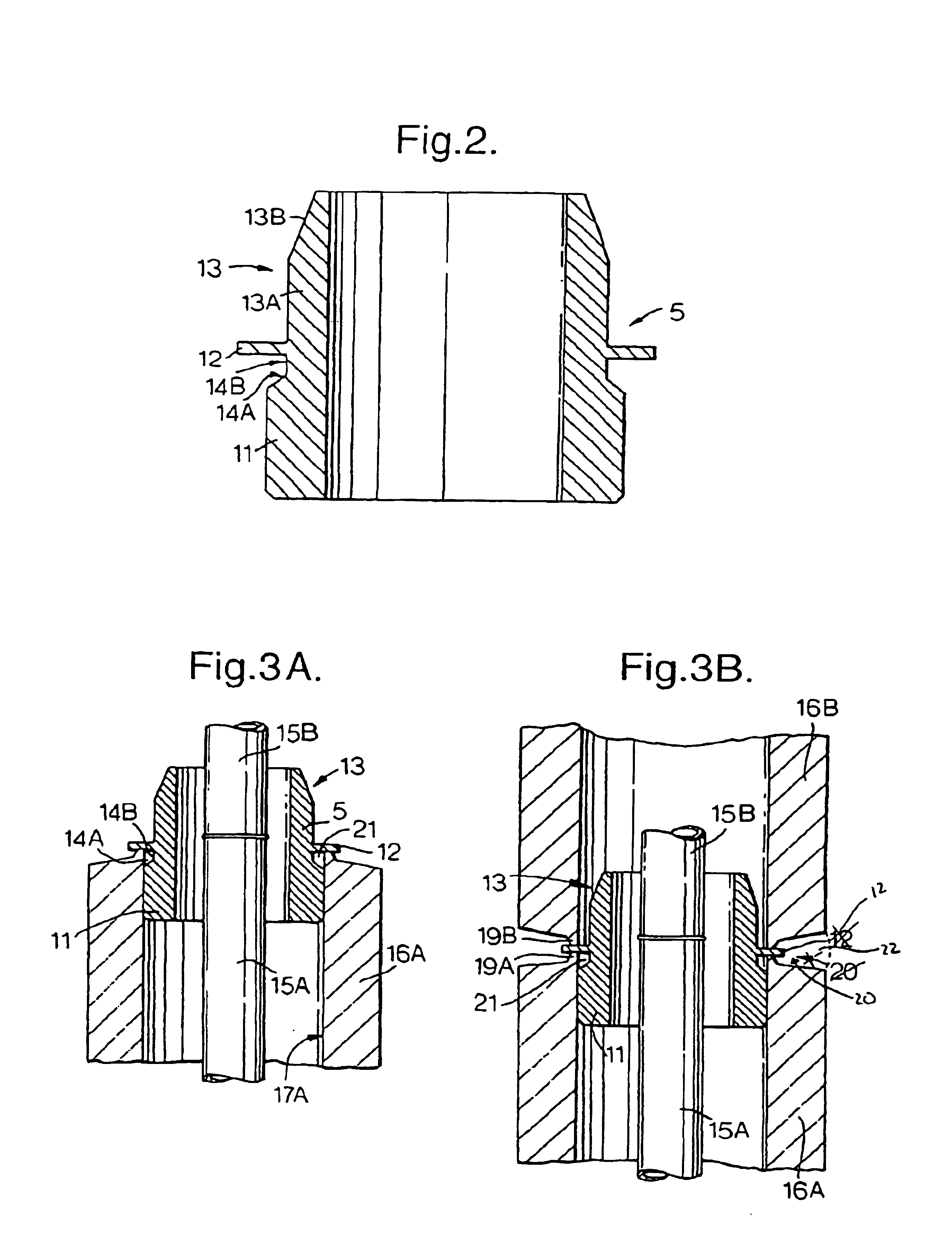
[0038]The general technique of J-laying is itself well known and will not be described further here. The distinctive aspect of the present invention concerns the use of an annular member or ring 5, shown in FIG. 2 during the step of welding together the confronting ends of the outer pipes of two pipe-in-pipe lengths of pipeline.

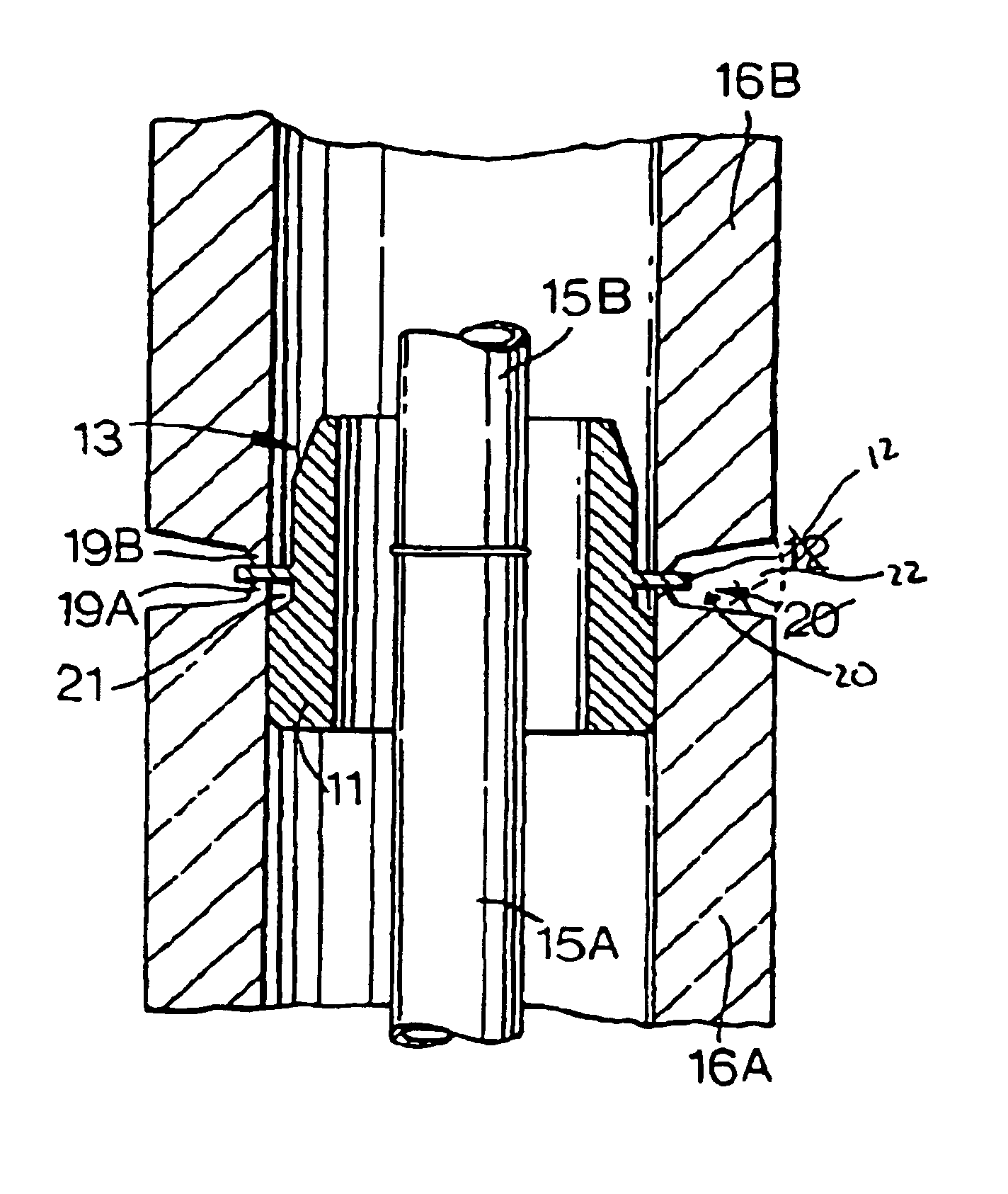
[0039]The ring 5 shown in FIG. 2 is made of steel and generally comprises a first axial part 11, a second flange part 12 and a th...


PUM


Abstract

A method of welding together the ends of outer pipe sections (16A, 16B) of pipe-in-pipe pipeline to be laid on a seabed employs an annular member (5) interposed between adjacent lengths of pipe. The annular member comprises a first axial part (11) which fits within the end of the first outer pipe section, and a flange part (12) which is interposed between the adjacent ends of the two lengths of outer pipe sections (16A, 16B) to be joined. The flange part (12) of the annular member (5) projects radially outwardly beyond the inside of the outer pipe sections (16A, 16B) and terminates radially inwardly of the outside of the outer pipe sections (16A, 16B), and provides some of the welding material for the joint.

Description

CROSS REFERENCE TO RELATED APPLICATION[0001]This application is a national stage of PCT / EP02 / 04195 filed on Mar. 26, 2002 and based upon United Kingdom 0107637.1 filed Mar. 27, 2001.BACKGROUND OF THE INVENTION[0002]1. Field of the Invention[0003]2. Description of the Related Art[0004]The invention relates to a method of laying a pipeline on a seabed and to a member for assisting in the laying of pipelines on a seabed.[0005]A traditional approach to laying pipelines at sea is a technique known as “S-laying”. This technique involves laying pipeline from a vessel with the pipeline inclined by a small inclination such as 5 or 10 degrees to the horizontal as it leaves the vessel.[0006]A more recent approach involves a technique known as “J-laying”, in which the pipeline leaves the vessel at a much steeper angle which may even be vertical. This method is especially suitable for laying a pipeline in deep water.[0007]A problem associated with J-laying is the means by which additional pipe s...

Claims


Application Information

Patent Timeline
IPC IPC(8): B23K37/053F16L13/02F16L13/00A61M39/00
CPCB23K37/0531F16L13/0227B23K2201/10B23K2101/10
Inventor TOSI, LUCIANOBONELLI, RENATO
Owner SAIPEM SPA
Why Eureka
Try Eureka