Temperature-controlled induction heating of polymeric materials

a technology of induction heating and polymer materials, applied in the direction of magnetism of inorganic materials, magnetic materials, magnetic bodies, etc., can solve the problem of temperature rising, and achieve the effect of increasing the heat, and increasing the hysteresis loop

Inactive Publication Date: 2005-09-06
TAS ACQUISITION CO
View PDF53 Cites 57 Cited by
  • Summary
  • Abstract
  • Description
  • Claims
  • Application Information

AI Technical Summary

Problems solved by technology

When a ferromagnetic material is placed in an electromagnetic field, the hysteresis losses in the material cause its temperature to rise, eventually reaching its Curie temperature.

Method used


Image

  • Temperature-controlled induction heating of polymeric materials
  • Temperature-controlled induction heating of polymeric materials
  • Temperature-controlled induction heating of polymeric materials

Examples


example 1

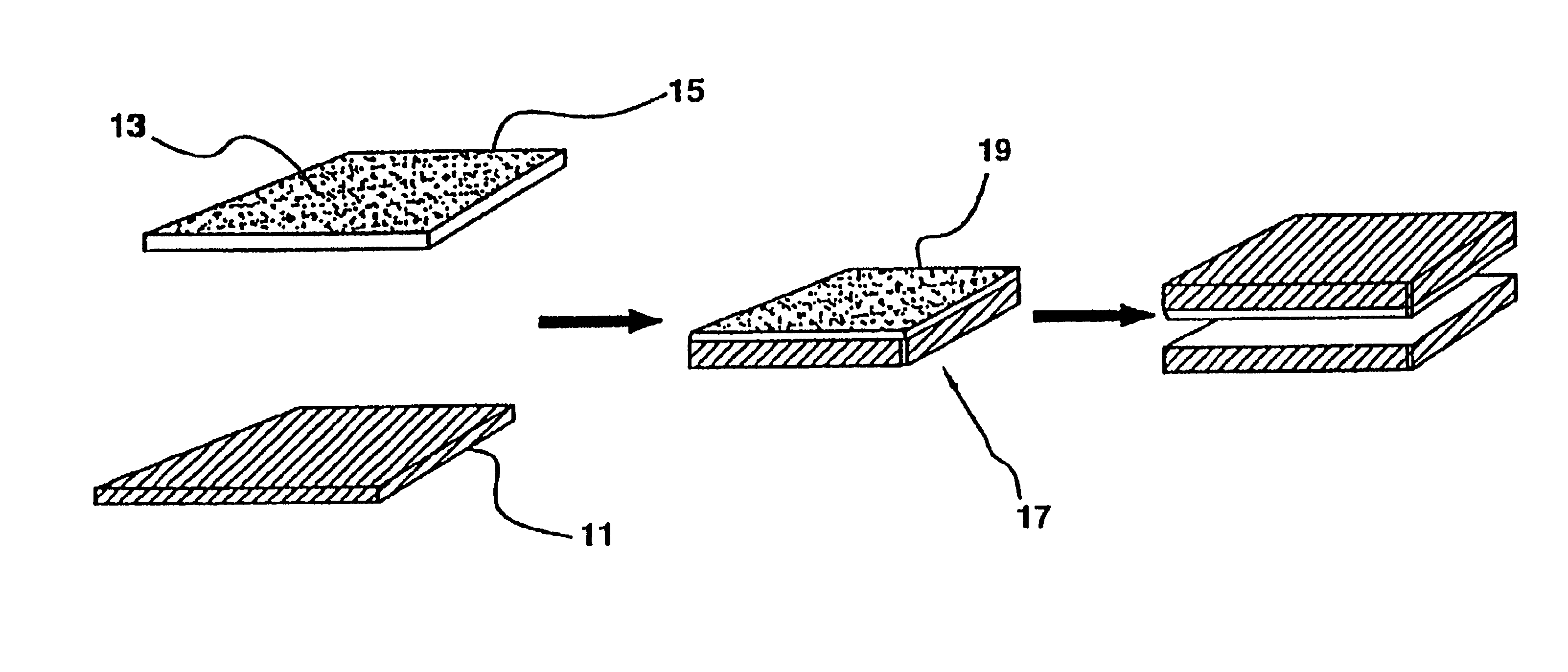
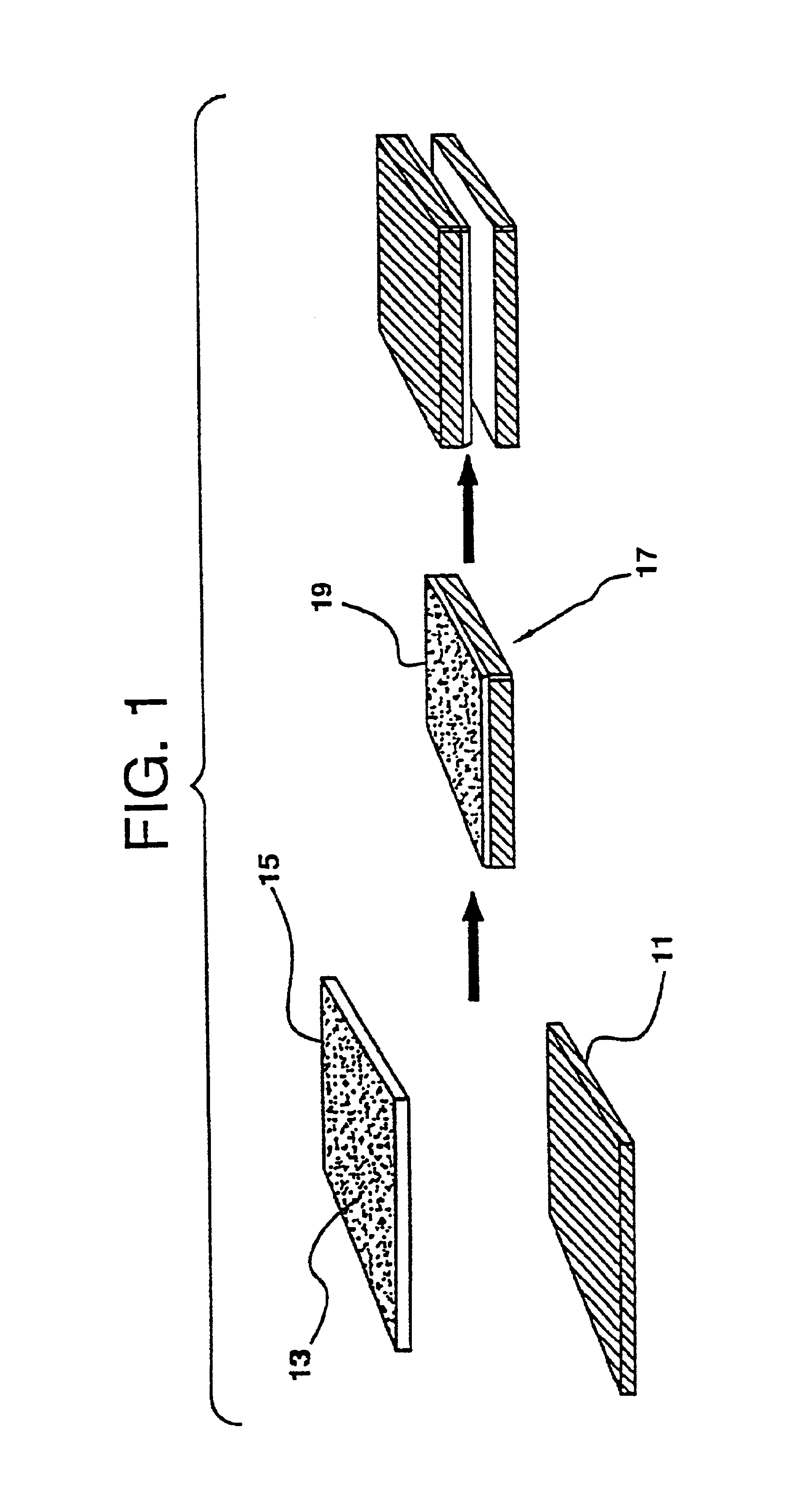
Extrusion Compounding / Compression Molding

[0111]The following compounds were successfully extruded and compression molded into sheets for evaluation in induction heating experiments:[0112]10, 12, and 15v / o. SrF in PSU[0113]15 and 30v / o SrF in PEEK[0114]15v / o SrF in PEI[0115]20v / o Co-2Y in PSU[0116]20v / o Mg-2Y in Nylon-6[0117]15v / o Zn1 / Mg1-2Y in Nylon-6

SrF was obtained from Steward Ferrite (Chattanooga, Tenn.), under the tradename HM 181.

example 2

Induction Heating Procedures

[0118]All induction heating trials were done using a Lepel model T-7.5-3-DF-SW induction generator with a solenoid coil. The coil (No. S 1L) was a 1″ ID, 15 turn design constructed from ⅛″ tubing that had total length of ˜2.4″. With this coil, and a representative sample in the coil, the generator operated at a frequency of 3.2 MHz and an estimated power of 2.3 KW. All heating trial samples consisted of a 1″ square of compound, approximately 20 mils thick that was taped to a glass slide. In order to prevent the slide from cracking due to thermal shock, a 1″ square of 1 / 16″ thick ceramic insulation was placed under all samples. All data was collected using a Raytek IR pyrometer that was set up to sight between 2 turns on the coil at the sample. The Raytek pyrometer was roughly calibrated by heating 51 and 30 Vol. % SrF / PSU samples painted with a strip of temper paint. The known melt temperature of the temper paint (800° F.) was correlated with the reading ...

example 3

[0121]Heating experiments were conducted with a Heuttinger induction generator that produces approximately 20 KW of output power at 2.3 MHz. The Lepel generator used in earlier heating experiments produced an estimated power output of only 2.3 to 5.8 Kw. With the Heuttinger generator, and employing pancake coils with 3 to 5 turns, the Curie temperature of 450° C. was reached in 15 to 30 seconds. The rapid heating phenomenon was confirmed with the Heuttinger generator for both bonded and non-bonded SrF.

[0122]Heating a virgin sample of 51 SrF / PSU to its Curie temperature without the application of a magnetic field (i.e., subjecting the sample to thermal energy only) does not produce rapid heating rates when heated a second time by induction.

[0123]Heating the susceptor inductively to temperatures below its Curie temperature also does not produce rapid heating rates when heated a second time by induction. To produce the rapid heating phenomenon, the susceptor must be preconditioned by ...


PUM

PropertyMeasurementUnit
sizeaaaaaaaaaa
Curie temperatureaaaaaaaaaa
curie temperatureaaaaaaaaaa

Abstract

The present invention provides new polymer induction bonding technology. Induction heating technologies are utilized to weld, forge, bond or set polymer materials. The invention provides controlled-temperature induction heating of polymeric materials by mixing ferromagnetic particles in the polymer to be heated. Temperature control is obtained by selecting ferromagnetic particles with a specific Curie temperature. The ferromagnetic particles will heat up in an induction field, through hysteresis losses, until they reach their Curie temperature. At that point, heat generation through hysteresis loss ceases. This invention is applicable to bonding thermoplastic materials, wherein only the area to be heated has ferromagnetic particles in it; bonding of thermoset composites, which have been processed with a layer of thermoplastic material on one side; curing of thermoset adhesives or composite resins; or consolidating thermoplastic composites.

Description

[0001]This application is a continuation-in-part of U.S. application Ser. No. 09 / 562,188, filed May 2, 2000, now abandoned which is a continuation-in-part of U.S. application Ser. No. 09 / 090,865, filed Jun. 5, 1998, and issued as U.S. Pat. No. 6,056,844, which claims the benefit of U.S. Provisional Application No. 60 / 048,919, filed Jun. 6, 1997.FIELD OF THE INVENTION[0002]The present invention relates to methods of controlled-temperature induction heating of polymeric materials by mixing ferromagnetic particles of particular compositions in the polymer to be heated. Temperature control is obtained by selecting ferromagnetic particles with specific Curie temperatures. The invention also relates to apparatuses for controlled temperature heating.BACKGROUND OF THE INVENTION[0003]As composite and polymer materials become more widely used in military and commercial vehicles and structures, more reliable and cost effective methods of fabrication and repair are required for those structures...

Claims


Application Information

Patent Timeline
Patent Type & Authority Patents(United States)
IPC IPC(8): B29C35/08B29C35/02B29C65/36B29C65/34C08K3/22C08K3/00
CPCB29C35/0272B29C35/08C08K3/22B29C65/3612B29C66/45B29C66/91651B29C66/91411B29C66/91431B29C66/91443B29C66/91445B29C2035/0811B29C2035/0816B29K2101/10B29K2101/12B29K2105/24B29C65/3676B29C66/452B29C65/3696B29C65/4815B29C66/1122B29C66/721B29C66/7392B29C66/7394B29C66/73941B29C66/71B29C66/73751B29C66/73753B29C66/73921B29L2031/7172B29K2077/00B29K2023/04B29K2023/10B29K2069/00B29K2075/00B29K2067/003B29K2071/00B29K2079/085B29K2067/00B29K2081/04B29K2081/06B29K2071/12B29K2023/12B29K2023/086B29K2023/06
Inventor STARK, PHILIPROSSI, GUY A.MOJAZZA, HAMID R.HAGHIGHAT, ROSSSCHULER, PETER
Owner TAS ACQUISITION CO
Why Eureka
Try Eureka