Permanent magnet rotor and brushless motor

a permanent magnet rotor and brushless motor technology, applied in the direction of magnetic circuit rotating parts, stator/rotor bodies, magnetic circuit shape/form/construction, etc., can solve the problems of demagnetization and resistance torque, and achieve the effect of suppressing magnet heat generation, reducing resistance torque, and reducing resistance torqu

Inactive Publication Date: 2005-09-06
HONDA MOTOR CO LTD
View PDF11 Cites 42 Cited by
  • Summary
  • Abstract
  • Description
  • Claims
  • Application Information

AI Technical Summary

Benefits of technology

[0011]In view of this circumstance, this invention intends to provide a permanent magnet rotor with relative large reluctance torque, improved accuracy of sensorless position detection and less magnet heat generation.

Problems solved by technology

In this configuration, since the rotor is provided with the protrusions, the reluctance torque can be made large; since the rotor is provided with the concaves, magnet heat generation can be suppressed, thereby making demagnetization difficult.

Method used


Image

  • Permanent magnet rotor and brushless motor
  • Permanent magnet rotor and brushless motor
  • Permanent magnet rotor and brushless motor

Examples


Embodiment Construction

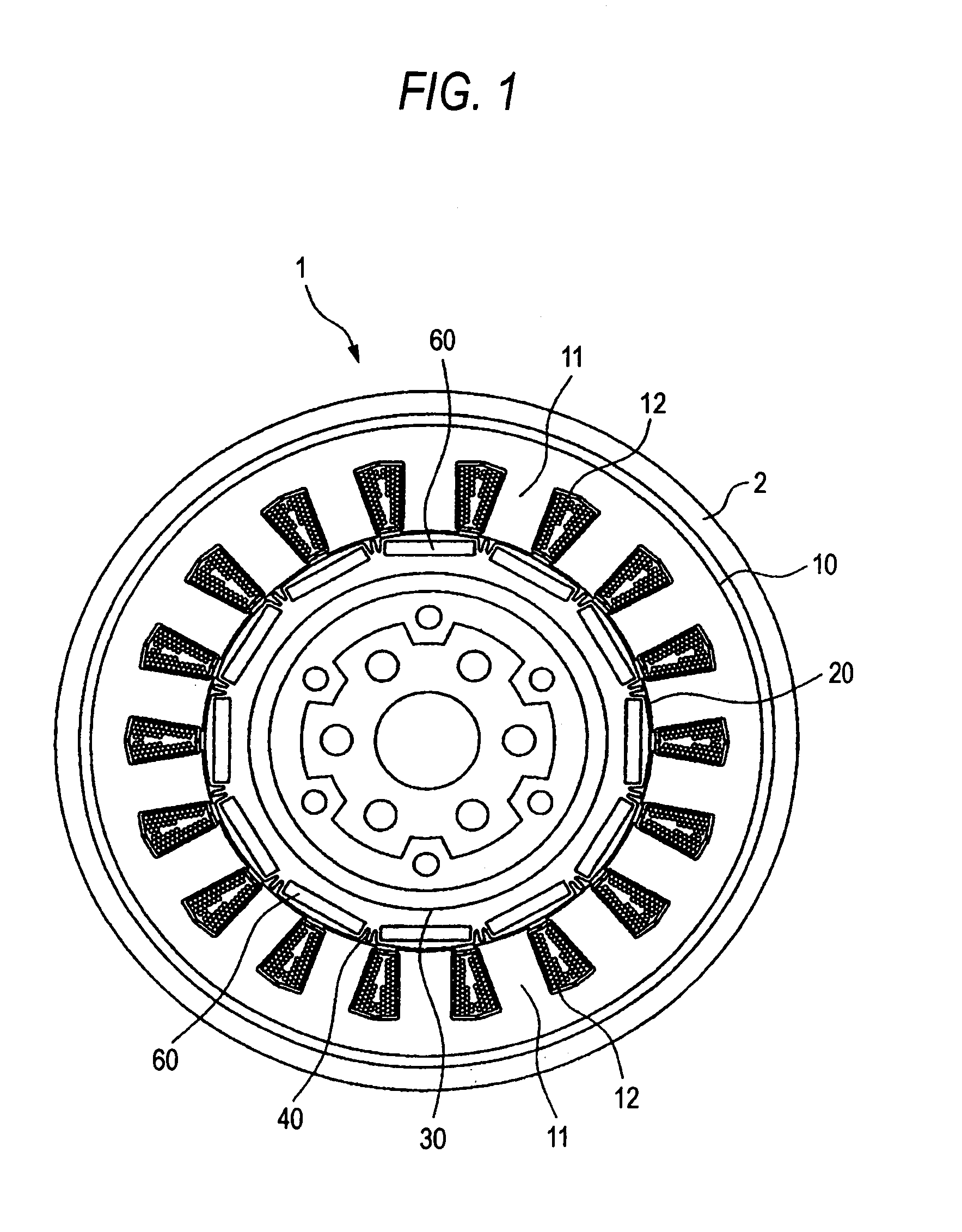
[0029]Now referring to the drawings from FIG. 1 to FIG. 7, an explanation will be given of a permanent magnet rotor according to this invention and a brushless motor equipped with such a rotor.

[0030]As seen from FIG. 1, a brushless motor 1 includes a stator 10 fixed to a casing 2 and a rotor (permanent magnet rotor) 20 rotatably supported by the casing 2. The stator 10 and rotor 20 are arranged concentrically and so as to be opposite in a radial direction.

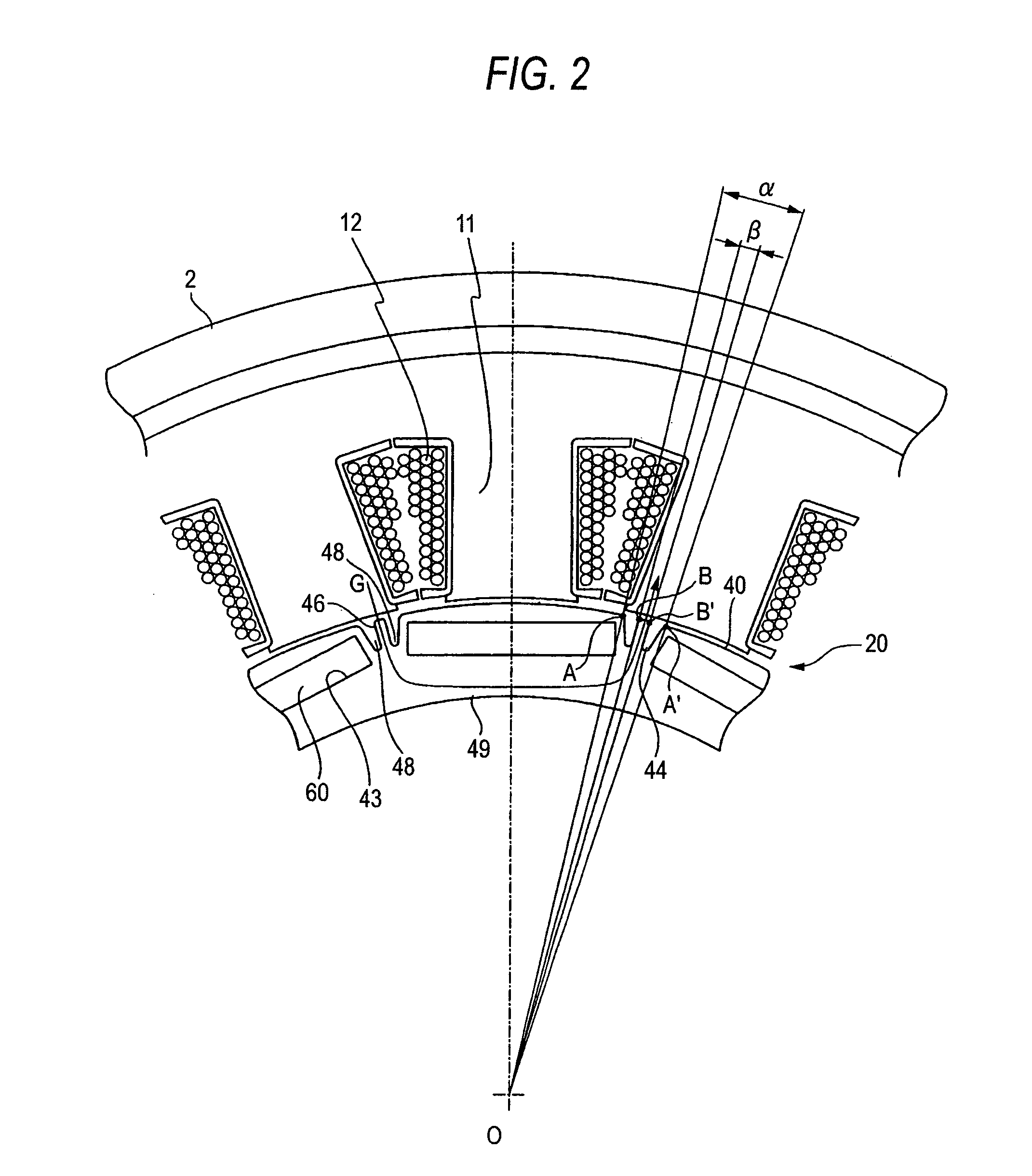
[0031]The stator 10 is formed in a cylindrical shape and has a plurality of teeth iron cores 11 projected inwardly in the radial direction. A winding 12 is wound around each teeth iron core 11.

[0032]The brushless motor 1 also includes a control device for estimating the position of the rotor 20 on the basis of the current flowing through each of windings in a multiple phase when a voltage for detecting the position of the rotor 20 is applied to the windings 12 of the stator 10, thereby being capable of detecting the position of the...


PUM

PropertyMeasurementUnit
sandwiching angleaaaaaaaaaa
voltageaaaaaaaaaa

Abstract

In a rotor 20 including a plurality of permanent magnet pieces 60 fixed in a plurality of magnet insertion slots 43 provided on the outer periphery of a rotor yoke 40, respectively, and the rotor yoke 40 having concaves 44 each provided between the permanent magnet pieces 60 adjacent to each other and protrusions 46 each provided in each the concaves 44 to protrude outwardly in the radial direction of the rotor yoke 40, between the sandwiching angle α formed by two sides connecting both outer ends A and A′ of each the concaves 44 to the center axis O of the rotor yoke 40 and the sandwiching angle β formed by two sides connecting both outer ends B and B′ of each the protrusions 46 to the center axis O of the rotor yoke 40, the following relationship is satisfied:0.3<β / α<0.5.

Description

BACKGROUND OF THE INVENTION[0001]This invention relates to a permanent magnet rotor having permanent magnets provided at a rotor iron core and a brushless motor equipped with such a rotor.[0002]As a rotor used for a motor, a permanent magnet rotor is known in which permanent magnets are provided at a plurality magnet attaching segments arranged at a rotor iron core. The permanent magnet rotor includes a type of having a convex (convex pole) between adjacent magnets (e.g. Patent Reference 1) and another type of having not the convex but a concave between the adjacent magnets (e.g. Patent Reference 2).[0003]Both types of permanent-magnetic rotors and brushless motors equipped with these rotors have advantages and disadvantages, respectively.[0004]The permanent magnet rotor of a type having the convex and brushless motor equipped with such a rotor have advantages that (1) reluctance torque is relatively large, and (2) the magnetic flux passes through the convex and hence easily passes ...

Claims


Application Information

Patent Timeline
Patent Type & Authority Patents(United States)
IPC IPC(8): H02K1/22H02K1/27H02K29/00H02K37/00H02K21/16H02K15/02H02K21/12
CPCH02K1/278Y10T29/49012
Inventor IMAMURA, TAKEHIRONAKAJIMA, MINORU
Owner HONDA MOTOR CO LTD
Why Eureka
Try Eureka