Concurrent phase communication in TWACS

a technology of twacs and communication channels, applied in the direction of powerline communication applications, signal transmission/receiving via power distribution, single ac networks with different frequencies, etc., can solve the problems of limiting the amount of information, delay in transmission and reception of outbound and outbound signals, etc., to increase the communication bandwidth of the network and speed up the system response

Active Publication Date: 2005-09-06
ACLARA TECH LLC
View PDF11 Cites 58 Cited by
  • Summary
  • Abstract
  • Description
  • Claims
  • Application Information

AI Technical Summary

Benefits of technology

[0007]A method for concurrently communicating over all of the phases of an electrical power distribution network. A first outbound signal is transmitted over one phasor of a three-phase bus by an outbound modulation unit. The outbound modulation unit is released as soon as the first outbound signal is transmitted. This allows the unit to now transmit a second outbound signal over another phasor of the bus with the second outbound signal being transmitted concurrently with an inbound signal returned in response to the first outbound signal transmitted over the first phase. The outbound modulation unit is again released, as soon as the second outbound signal is transmitted, so the unit can now transmit a third outbound signal over the third phasor of the bus. This third outbound signal is transmitted concurrently with a second inbound signal, returned in response to the second outbound signal transmitted over the second phase. The method allows concurrent communications over all three phases of the network substantially increasing the communications bandwidth of the network and allowing for faster system response to changes in electrical demand. Further, the method is repeated so long as there are commands to be processed.

Problems solved by technology

The problem this presents is the delay in the transmission and reception of outbound and inbound TWACS signals, and the consequent limiting of the amount of information, which can be sent and received through the system at any one time.

Method used


Image

  • Concurrent phase communication in TWACS
  • Concurrent phase communication in TWACS
  • Concurrent phase communication in TWACS

Examples


Embodiment Construction

[0015]The following detailed description illustrates the invention by way of example and not by way of limitation. This description will clearly enable one skilled in the art to make and use the invention, and describes several embodiments, adaptations, variations, alternatives and uses of the invention, including what we presently believe is the best mode of carrying out the invention. As various changes could be made in the above constructions without departing from the scope of the invention, it is intended that all matter contained in the above description or shown in the accompanying drawings shall be interpreted as illustrative and not in a limiting sense.

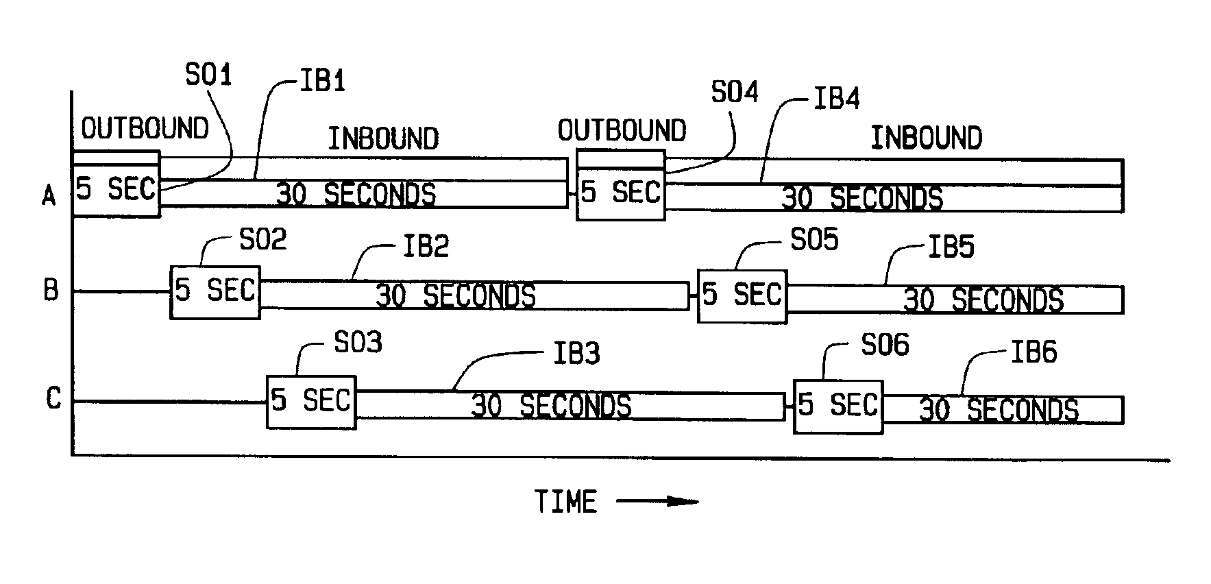
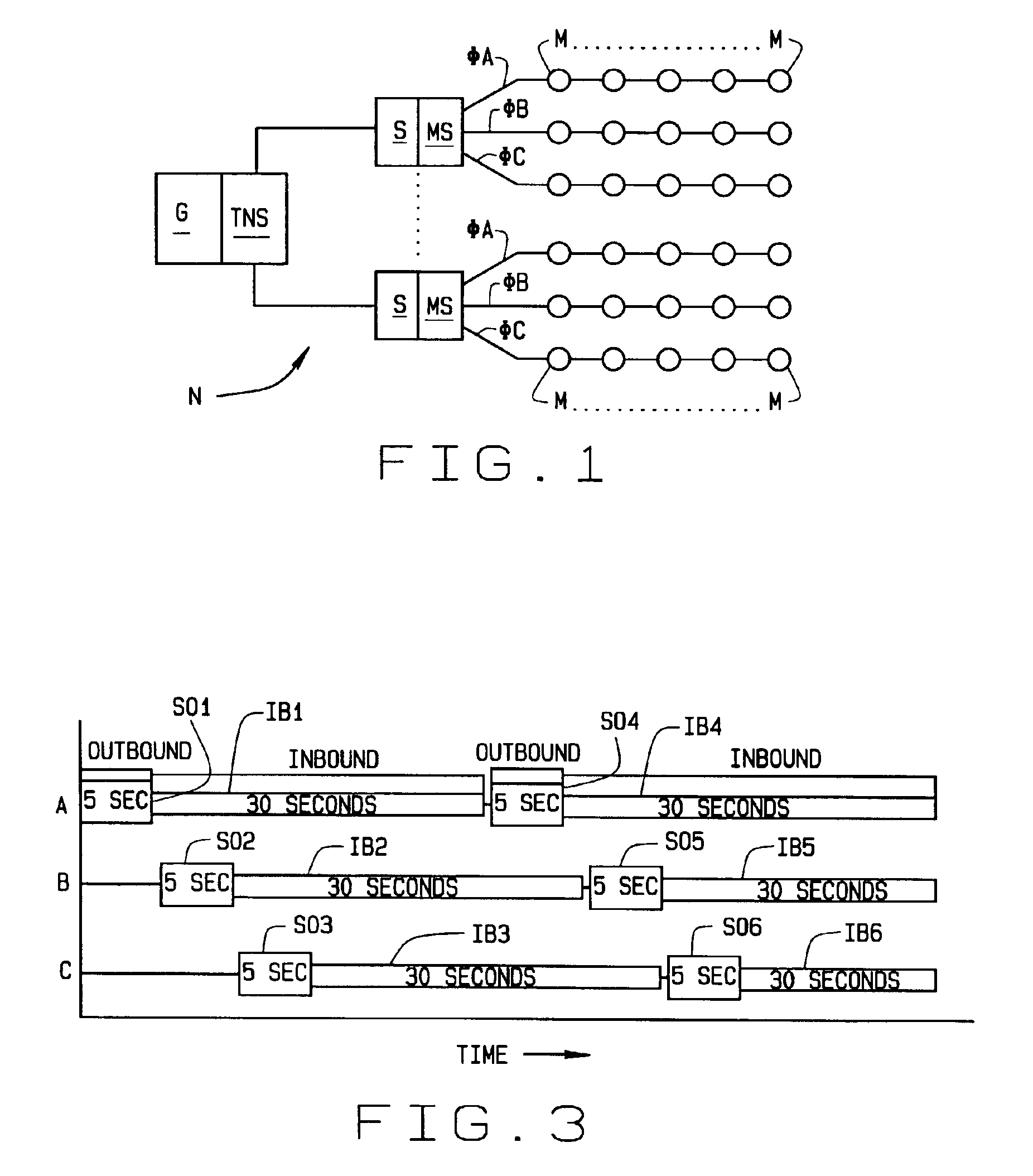
[0016]Referring to the drawings, an electrical power distribution network N includes a power generating plant G whose electrical output is distributed through a series of substations S. Each substation supplies power to a number of homes, office buildings, factories, etc. Each building is equipped with an electrical meter M d...


PUM


Abstract

A method for concurrently communicating over each phase of an electrical power distribution network (N). A first outbound signal (SO1) is transmitted over one phase (AN-A) of a bus (S) by an outbound modulation unit. The unit is released as soon as the first outbound signal (SO1) is transmitted so the unit can transmit a second outbound signal (SO2) over a second phase (BN-B or CN-C) of the bus. The second outbound signal is transmitted concurrently with an inbound signal (IB1) sent in response to the first outbound signal (SO1). The unit is again released, as soon as the second outbound signal (SO2) is transmitted, so the unit can transmit a third outbound signal (SO3) over the third phase (BN-B or CN-C) of the bus. This third outbound signal is transmitted concurrently with a second inbound signal (IB2) sent in response to the second outbound signal (SO2). The method allows concurrent communications over all three phases of the network (N).

Description

CROSS REFERENCE TO RELATED APPLICATIONS[0001]NoneSTATEMENT REGARDING FEDERALLY SPONSORED RESEARCH OR DEVELOPMENT[0002]N / ABACKGROUND OF THE INVENTION[0003]This invention relates to the transmission of signals on a multi-phase (3φ) power transmission system using a two-way communications system (TWACS®), and more particularly to the concurrent transmission of data and other information on more than one of the phases.[0004]It is known to transmit and receive messages on an electrical distribution system. Patents teaching a two-way communications system and the techniques employed in two-way communication include U.S. Pat. Nos. 5,696,441, 5,486,805, 5,262,755, 4,996,513, 4,963,853, 4,918,422, 4,914,418, and 4,658,238 all of which are assigned to the same assignee of the present application. In practice, a request for information or data is formulated into an “outbound” message that is injected into one phase of a three-phase power distribution network and transmitted through the network...

Claims


Application Information

Patent Timeline
Patent Type & Authority Patents(United States)
IPC IPC(8): H04B3/54H04L12/28
CPCH04B3/54H04B3/542H04B2203/5416H04B2203/5433H04B2203/5466
Inventor HAMMOND, BENJAMIN A.HESSLING, JR., JOHN B.LAGERSTROM, KRISTER
Owner ACLARA TECH LLC
Why Eureka
Try Eureka