RFID device and method of forming

a technology of rfid devices and antennas, applied in the direction of shielding material radiating elements, device details, instruments, etc., can solve the problems of slow and/or difficult methods of attaching electronics to the antenna, and difficulties in assembly

Inactive Publication Date: 2005-09-06
AVERY DENNISON CORP
View PDF55 Cites 221 Cited by
  • Summary
  • Abstract
  • Description
  • Claims
  • Application Information

AI Technical Summary

Problems solved by technology

One problem with current assembly methods is that methods of attaching the electronics to the antenna may be slow and / or difficult due to accuracy requirements for placing the electronics, especially small electronics, on the antenna.
Also, difficulties in assembly may arise from long cure times and / or expensive materials used in adhesives for attaching the electronics to the antenna.

Method used


Image

  • RFID device and method of forming
  • RFID device and method of forming
  • RFID device and method of forming

Examples


Embodiment Construction

RFID Inlays

[0043]By way of overview, the present invention involves structures and method for operatively coupling parts of an RIFD inlay together. Specifically, the invention relates to conductive connections between an RFID antenna and a strap that is in turn operatively coupled to a chip, such as an integrated circuit chip. The conductive connection may include conductive bumps attached to the strap, and / or may include conductive traces, such as a conductive ink traces. The conductive connections provide a convenient, fast, and effective way to operatively couple antennas and straps.

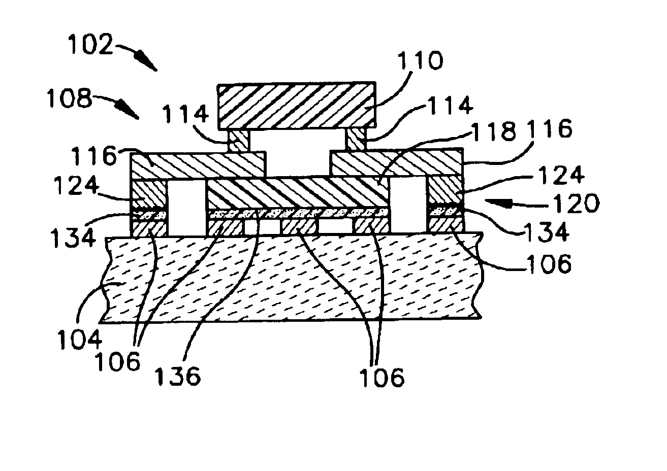
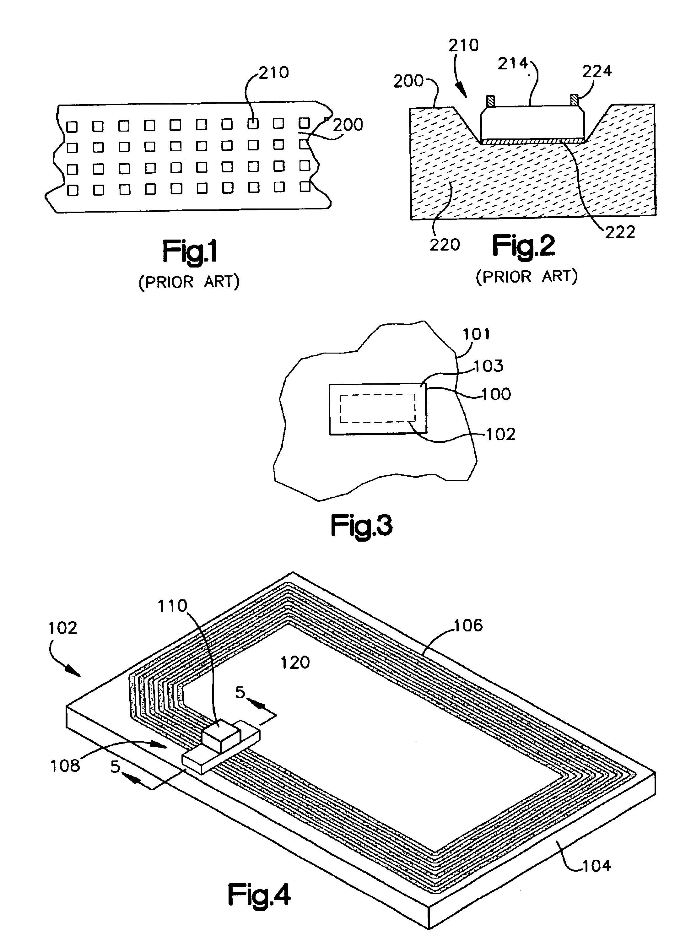
[0044]Referring initially to FIG. 3, an RFID tag or label 100 is adhered or otherwise coupled to an object 101. The RFID tag or label 100 includes an RFID inlay 102 and a printable facestock 103. The RIFD inlay 102 as used herein may include a variety of active and passive RFID devices.

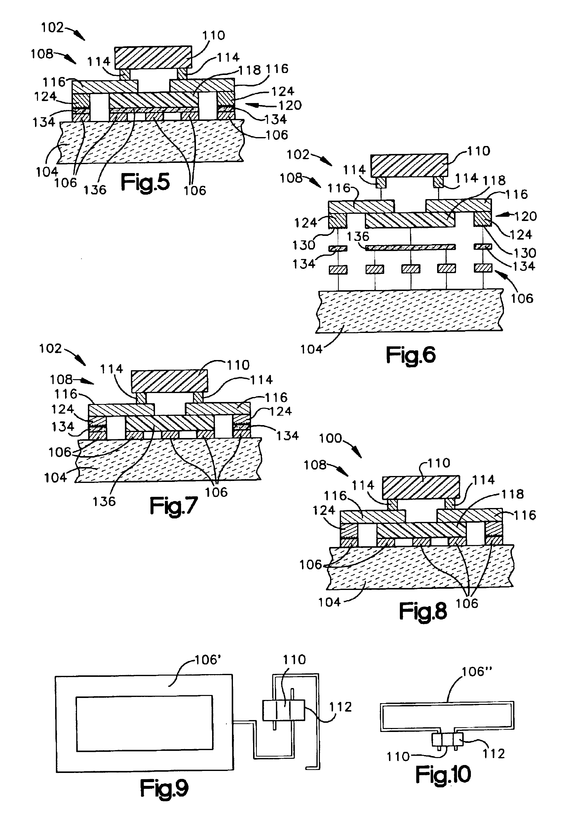
[0045]Referring now and in addition to FIGS. 4-6, further details of the RFID inlay 102 are shown. The RFID inlay 102...


PUM


Abstract

A radio frequency identification (RFID) inlay includes a conductive connection electrically connecting an antenna to strap leads that are coupled to an RFID chip. The conductive connection may include conductive bumps attached to the strap, and / or may include conductive traces, such as a conductive ink traces. The conductive connections provide a convenient, fast, and effective way to operatively couple antennas and straps. The RFID inlay may be part of an RFID label or RFID tag.

Description

BACKGROUND OF THE INVENTION[0001]1. Field of the Invention[0002]This invention relates to the field of radio frequency identification (RFID) tags and labels, and to particular configuration of such devices and methods of manufacturing such devices.[0003]2. Description of the Related Art[0004]RFID tags and labels have a combination of antennas and analog and / or digital electronics, which may include for example communications electronics, data memory, and control logic. RFID tags and labels are widely used to associate an object with an identification code. For example, RFID tags are used in conjunction with security-locks in cars, for access control to buildings, and for tracking inventory and parcels. Some examples of RFID tags and labels appear in U.S. Pat. Nos. 6,107,920, 6,206,292, and 6,262,292, all of which this application incorporates by reference.[0005]RFID tags and labels include active tags, which include a power source, and passive tags and labels, which do not. In the c...

Claims


Application Information

Patent Timeline
Patent Type & Authority Patents(United States)
IPC IPC(8): G06K19/077H01Q1/22H01Q1/38H01Q7/00
CPCG06K19/07749G06K19/07752H01Q1/22H01Q1/2225H01Q1/38H01Q7/00H01L2924/15153
Inventor FERGUSON, SCOTT WAYNEEDWARDS, DAVID N.
Owner AVERY DENNISON CORP
Why Eureka
Try Eureka