Belt device and unit device including belt device and image forming apparatus using the belt device and unit device

a technology of image forming apparatus and belt device, which is applied in the direction of electrographic process apparatus, instruments, optics, etc., can solve the problems of unfavorable development, unfavorable development, and scattering of developers, so as to prevent inconveniences

Inactive Publication Date: 2005-09-06
RICOH KK
View PDF48 Cites 20 Cited by
  • Summary
  • Abstract
  • Description
  • Claims
  • Application Information

AI Technical Summary

Benefits of technology

[0017]The present invention advantageously provides a novel image forming apparatus, an image forming unit device having a belt-formed member and a belt device for use in the image forming apparatus, for preventing inconveniences caused by unnecessary contact of the belt-formed member with opposing members, or proximity of the two members by making it possible to separate the belt-formed member from part of the opposing members.
[0018]The present invention also advantageously provides a novel image forming apparatus, an image forming unit device having a belt-formed member and a belt device for use in the image forming apparatus, for driving the belt-formed member accurately even when the belt-formed member is separated from part of a plurality of opposing members located in close proximity to the belt-formed member or contacting the belt-formed member.

Problems solved by technology

When a single color image forming operation is performed in the above-described electrophtographic copying machine having selectable single color and multicolor modes, inconveniences may be caused because the photoconductive elements which are not involved in the image forming operation are located in contact with or in close proximity to the intermediate transfer element.
Developer remaining on the photoconductive elements may also adhere to a surface of the intermediate transfer element, which results in unnecessary consumption of developer.
Further, the above-described scattering of developer and unnecessary consumption of the developer occur not only when the plurality of opposing members are located side by side in a line opposing and contacting the belt-formed member but also when the plurality of opposing members are located side by side in a line opposing the belt-formed member in close proximity.
When the intermediate transfer element is driven while the tension has varied, the intermediate transfer element may not be driven accurately.
For example, when the intermediate transfer element is frictionally driven by rubber rollers, if the tension of the intermediate transfer element is decreased, the intermediate transfer element may not be accurately driven by the rubber rollers due to slides of the intermediate transfer element over the rubber rollers.
Contrarily, if its tension is increased, a driving load imposed on the intermediate transfer element may become too excessive to drive the intermediate transfer element accurately.
The above-described inconvenience of inaccurate drive of a belt-formed intermediate transfer element due to a variation in the tension of the intermediate transfer element may be caused not only when a plurality of photoconductive elements are disposed side by side in a line opposing and contacting the belt-formed intermediate transfer element as described above, but also when a plurality of opposing members are arranged side by side in a line opposing and contacting or in close proximity to a belt-formed member supported by a plurality of supporting rollers frictionally driven while being temporarily separated from part of the plurality of opposing members.
For example, the inconvenience may also be caused when a belt-formed photoconductive element is driven while being separated from part of a plurality of developer bearing members as a plurality of opposing members or when a belt-formed transfer sheet conveying member is driven while being temporarily separated from part of a plurality of photoconductive elements as a plurality of opposing members.
Further, the inconvenience may also be caused not only when the plurality of opposing members are arranged side by side in a line so as to contact the belt-formed member but also when they are arranged side by side in a line so as to oppose the belt-formed member in close proximity.

Method used


Image

  • Belt device and unit device including belt device and image forming apparatus using the belt device and unit device
  • Belt device and unit device including belt device and image forming apparatus using the belt device and unit device
  • Belt device and unit device including belt device and image forming apparatus using the belt device and unit device

Examples


Embodiment Construction

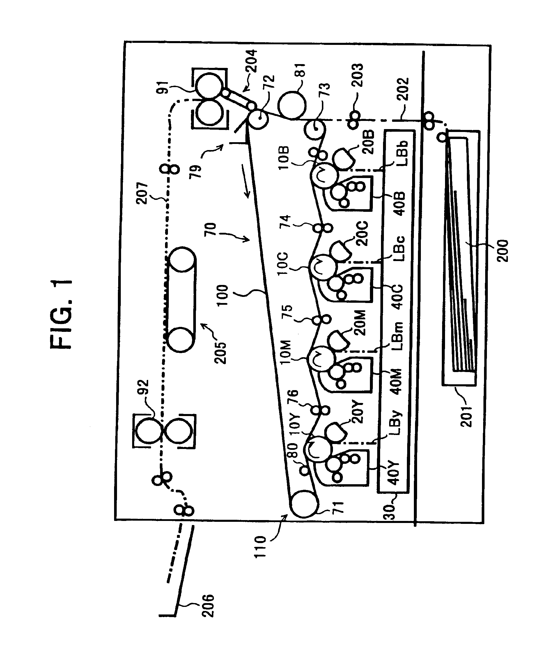
[0049]Referring now to the drawings, wherein like reference numerals designate identical or corresponding parts throughout the several views, FIG. 1 is a schematic drawing illustrating an internal construction of an electrographic multicolor printer with liquid developer (hereinafter referred to as printer) as an example of an image forming apparatus according to an embodiment of the present invention. The printer receives image data from a personal computer (PC) etc., and performs a printing process.

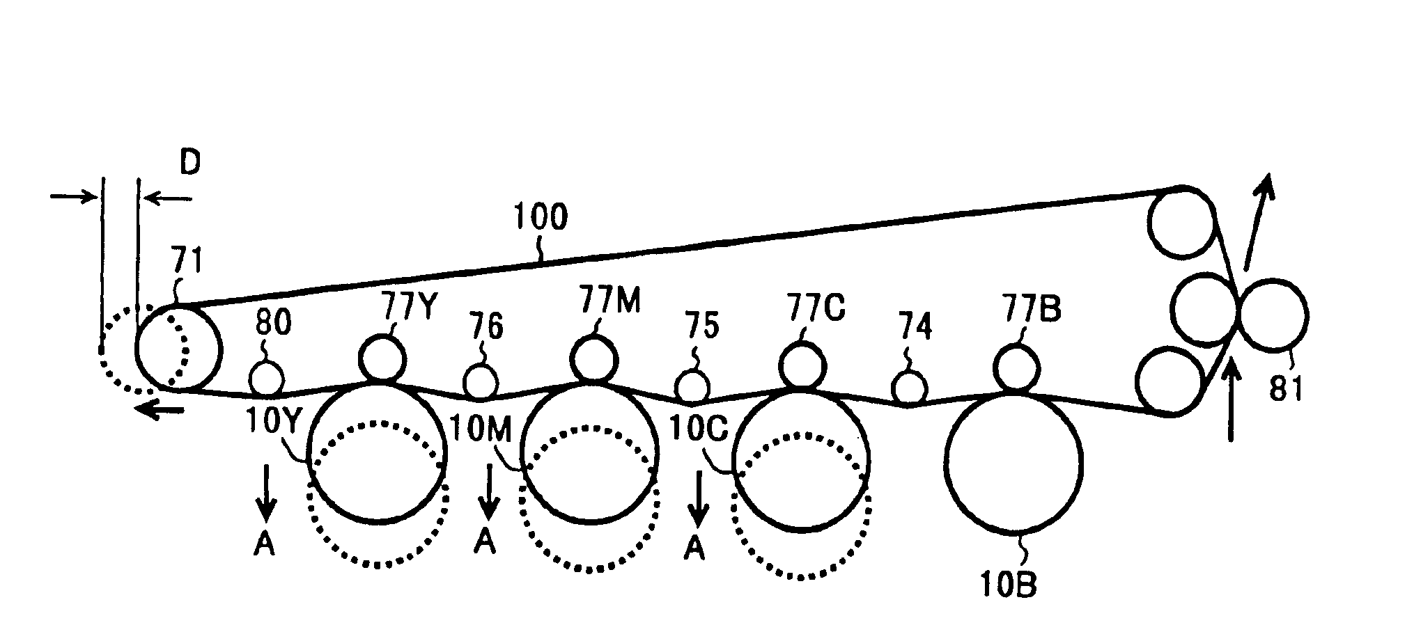
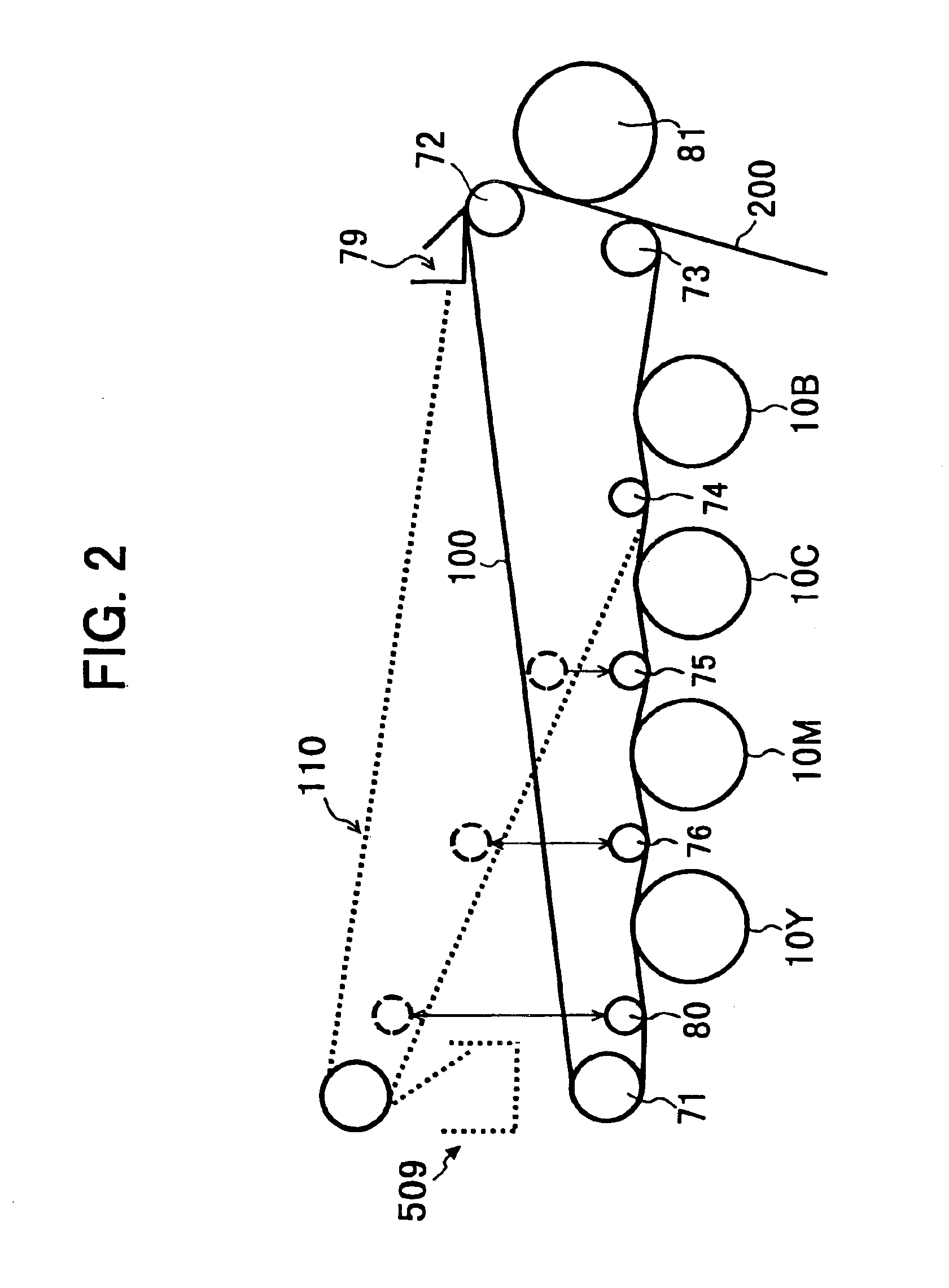
[0050]As illustrated in FIG. 1, four drum-shaped photoconductive elements 10Y, 10M, 10C and 10B, as opposing members (latent image bearing members), corresponding to respective colors of yellow Y, magenta M, cyan C and black B, are disposed side by side in a line. Each axis of rotation of the photoconductive elements 10Y, 10M 10C and 10B is located in the same plane and in parallel with each other axis. The photoconductive element 10B for a black color mode (single color mode) is locate...


PUM


Abstract

An image forming apparatus suppresses several kinds of inconveniences caused by unnecessary contact of a belt-formed member with opposing members and drives the belt-formed member accurately even when the belt-formed member separated from a part of a plurality of opposing members. In an image forming apparatus having a belt-formed member supported by a plurality of supporting rollers and a plurality of opposing members located side by side in a line to oppose and contact the belt-formed member, a pivot mechanism is employed to temporarily separate the belt-formed member from a part of the opposing members for color image formation. The image forming apparatus also includes a tension roller dive mechanism to increase a relative distance between the tension roller and other supporting rollers to suppress a decrease in a tension of the belt-formed member during the above-described separation of the belt-formed member from the plurality of opposing members.

Description

CROSS-REFERENCE TO RELATED APPLICATIONS[0001]This document claims priority and contains subject matter related to Japanese Patent Applications Nos. JPAP11-166288 filed on Jun. 14, 1999, JPAP11-365318 filed on Dec. 22, 1999 and JPAP2000-114451 filed on Apr. 14, 2000, and the entire contents thereof are herein incorporated by reference.BACKGROUND OF THE INVENTION[0002]1. Field of the Invention[0003]The present invention relates to an image forming apparatus such as, a copying machine, a facsimile, a printer, etc., and more particularly to an image forming unit device including a belt-formed member and a belt device in which the belt-formed member drives accurately even when the belt-formed member temporarily separates from some of opposing members.[0004]2. Discussion of the Background[0005]As an image forming apparatus, a tandem multicolor image forming apparatus, that includes an intermediate transfer element supported by a plurality of supporting rollers and a plurality of photocond...

Claims


Application Information

Patent Timeline
Patent Type & Authority Patents(United States)
IPC IPC(8): G03G15/01G03G15/16G03G15/00G03G15/08G03G21/00
CPCG03G15/0131G03G15/1605G03G2215/0119G03G2215/0132G03G2215/0193G03G15/1615
Inventor SASAMOTO, TETSUROUMIYAWAKI, KATSUAKIOBU, MAKOTOSUZUKI, MINORUAOYAMA, YUICHI
Owner RICOH KK
Why Eureka
Try Eureka