Eureka AIR delivers breakthrough ideas for toughest innovation challenges, trusted by R&D personnel around the world.

Method for mounting an arm to an actuator

Inactive Publication Date: 2005-09-13
INTRI PLEX (THAILAND) LTD
View PDF17 Cites 12 Cited by
  • Summary
  • Abstract
  • Description
  • Claims
  • Application Information

AI Technical Summary

Benefits of technology

[0014]In a second embodiment, the present invention is a disk drive having at least one disk rotatably mounted to a motor, a voice coil motor, an actuator coupled to the voice coil motor, and an actuator assembly coupled to the actuator. The actuator assembly includes a spindle mounted to the actuator and a first spacer mounted to the spindle. The first spacer includes a flange having a first planar surface and an opposite planar surface. An aperture extends between the first and second planar surfaces, and the spindle is inserted through the aperture. A lip extends from the first planar surface and surrounds the aperture of the spacer. A first arm is mounted to the spacer, with the arm having first and second resilient fingers at the proximal en

Problems solved by technology

In addition, a large vertical force must be used to swage the boss to the actuator arm, which can warp or otherwise permanently deform the actuator assembly.
Suspensions that are swaged to the actuator block also cannot easily be selectively reworked or replaced due to the nature of the swaging process.
One shortcoming of an actuator assembly having such a stacked array is that, should one or more of the head suspensions on the arms fail, it is cumbersome to replace the arm having the failed suspension.
For example, while it is possible to selectively rework an individual actuator arm having a head suspension attached thereto without disassembling the stacked array, it can be difficult to grasp the individual actuator arm due to the relatively close spacing between arms, and damage to surrounding arms and / or suspensions can result.
This problem is exacerbated by the general industry trend toward smaller storage devices, which further reduces the room between individual arms and suspensions, making it more difficult to grasp the arms.
Manufacturing tolerances on the machining of the grooves can, however, introduce errors into the Z-height of the arm / suspension components.

Method used


Image

  • Method for mounting an arm to an actuator
  • Method for mounting an arm to an actuator
  • Method for mounting an arm to an actuator

Examples


Embodiment Construction

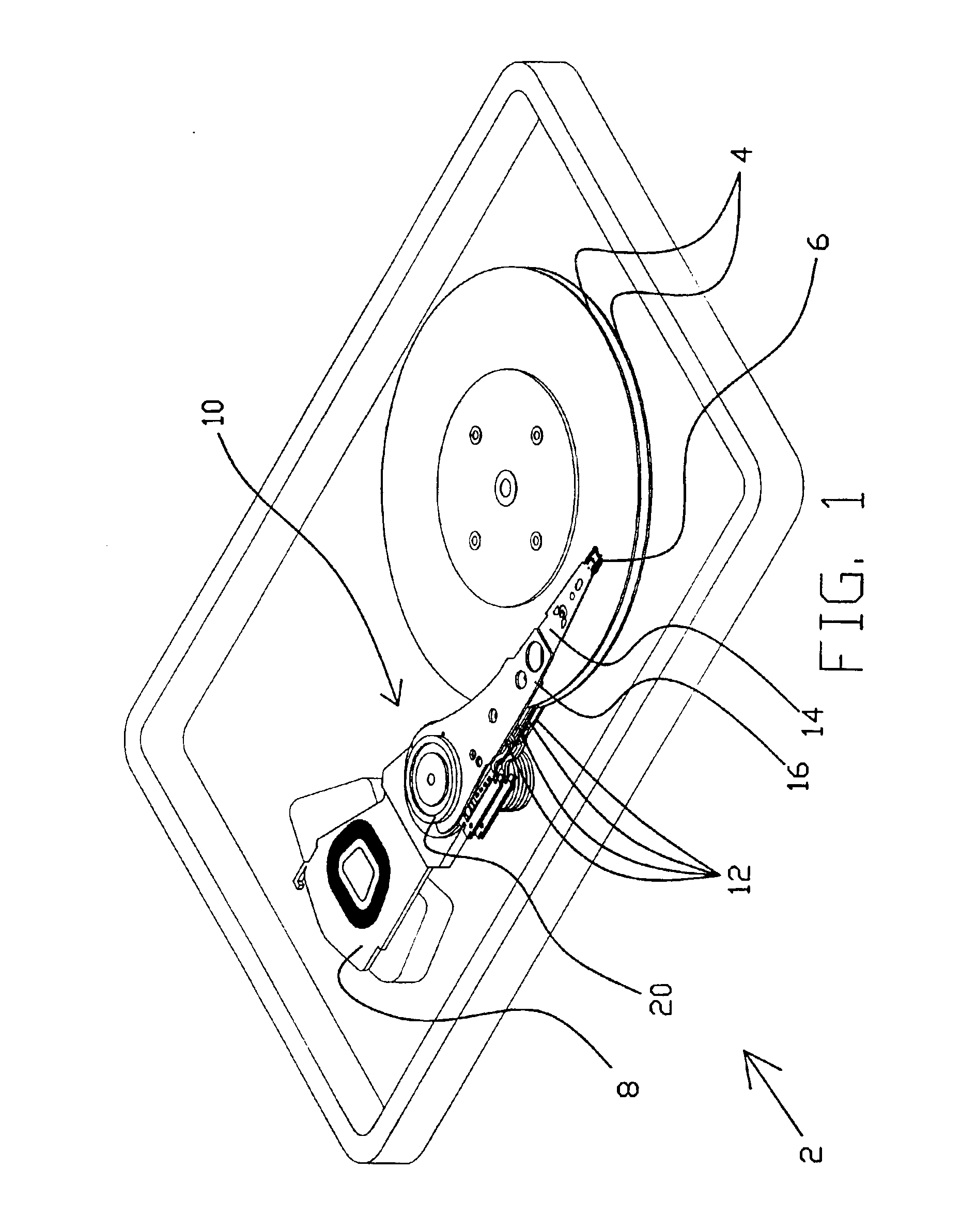
[0026]Referring now to FIG. 1, a disk drive 2 having a plurality of magnetic disks 4 is shown. Disk drive 2 includes an actuator assembly 10 that positions a plurality of magnetic heads 6 over the disks to read data from the disks and to write data to the disks. Typically, a single head 6 is positioned over an individual surface of each of the disks 4, and thus each disk 4 will have a pair of heads 6 associated with the disk. Actuator assembly 10 is coupled to a voice coil motor 8 that rotates assembly 10 in response to commands received by the voice coil motor by a microprocessor (not shown). In this manner, the actuator assembly 10 positions the heads 6 over a desired location of disks 4.

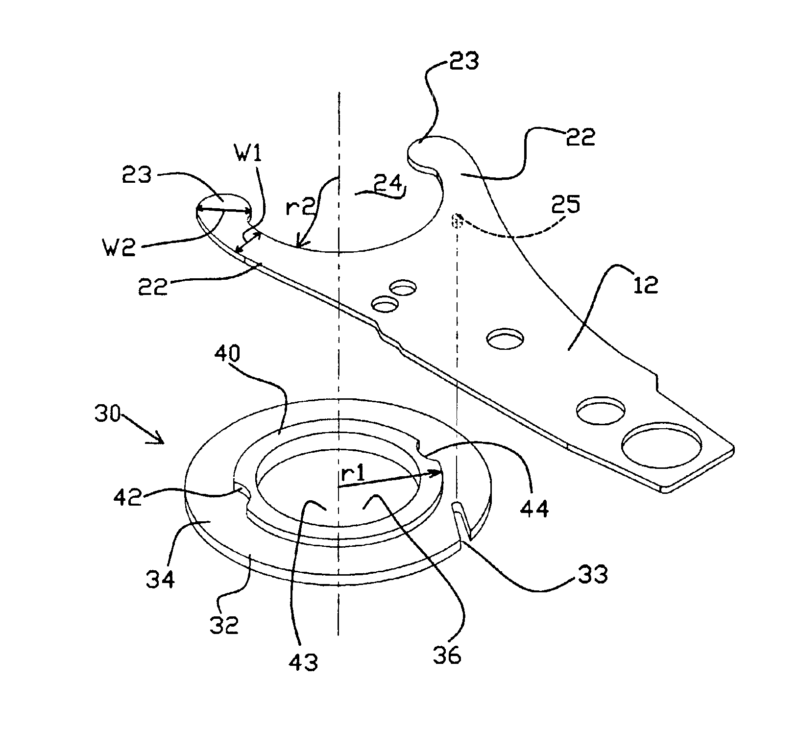
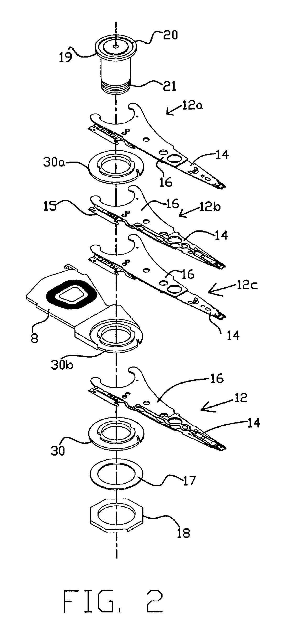
[0027]More specifically, actuator assembly 10 includes a stacked array of arms 12, with each arm 12 supporting one of the plurality of heads 6. Each arm 12 includes a head suspension 14 and an actuator arm 16. The head 6 is mounted to a distal end of the head suspension 14, and head suspension 14 ...


PUM

PropertyMeasurementUnit
Diameteraaaaaaaaaa
Radiusaaaaaaaaaa
Resilienceaaaaaaaaaa

Abstract

A method for mounting removably secured actuator arms that include head suspensions to an actuator assembly spindle. Each arm is mounted to an actuator spindle via a spacer with an annular lip with at least one detent formed into its perimeter edge. Each actuator arm includes two resilient fingers, annularly shaped to form an interior radius smaller than the spacer radius with at least one engagement member formed into a finger. Each arm is mounted by expanding the resilient fingers to a stressed state, engaging the fingers with the lip, and positioning the fingers so that each engagement member is aligned and engaged with a detent. The spacer alternatively includes a guide slot in a planar surface from which the lip extends, with the guide slot being engaged by a boss tower on the arm to properly orient the arm when mounting the arm to the spacer.

Description

REFERENCE TO RELATED APPLICATION[0001]This application is a division of application Ser. No. 09 / 501,433, filed on Feb. 10, 2000, now U.S. Pat. No. 6,456,463, which is hereby incorporated by reference in its entirety.TECHNICAL FIELD[0002]The present invention relates generally to an actuator assembly in an information storage device. In particular, the invention is an actuator assembly having an actuator arm mounted to a spacer of the actuator assembly.BACKGROUND OF THE INVENTION[0003]Information storage devices are in wide spread use, and are used to store and retrieve large amounts of data. Such information storage devices generally include a rigid media for storing information, a read / write device for creating and accessing the information, and an actuator assembly for positioning the read / write device over the rigid media. One common example of such an information storage device is a hard disk drive having one or more rotating magnetic disks, over a surface of each of which a hea...

Claims


Application Information

Patent Timeline
IPC IPC(8): G11B5/48
CPCG11B5/4813Y10T29/49904Y10T29/49032Y10T29/49025
Inventor VAN SLOUN, SHANE J.
Owner INTRI PLEX (THAILAND) LTD
Why Eureka
Eureka Blog
Learn More