Drive device for packaging machine

a drive device and packaging machine technology, applied in the direction of packaging, packaging goods type, application, etc., can solve the problems of increasing the cost of packaging machines in its entirety, requiring labor and time to alter the operation curve, and reducing the operating members usable with the drive device, so as to reduce the overall cost of packaging machines, reduce labor required, and improve the effect of operation stability

Inactive Publication Date: 2005-09-13
SHIKOKU KAKOOKI CO LTD
View PDF3 Cites 12 Cited by
  • Summary
  • Abstract
  • Description
  • Claims
  • Application Information

AI Technical Summary

Benefits of technology

[0006]An object of the present invention is to provide a fluid pressure actuator which is usable for a wider variety of applications as a drive device for operating members of packaging machines so as to achieve a reduction in the overall cost of the packaging machine, and which is improved in operation stability and greatly reduced in the labor required for the adjustment of the actuator as a drive device.

Problems solved by technology

Drive devices wherein a cam or like mechanical means is used are suitable for causing an operating member to perform an accurate movement but have the problem of being complex in construction or requiring labor and time for altering the operation curve.
However if many drive devices comprising a servo motor or the like are used, there arises the problem that the packaging machine becomes expensive in its entirety.
Although inexpensive, drive devices comprising an air cylinder or like fluid pressure cylinder are not comparable to the drive devices of the above two types with respect to operation stability, require much labor for adjustment and therefore have the problem that the operating members usable with the drive device are limited.

Method used


Image

  • Drive device for packaging machine
  • Drive device for packaging machine
  • Drive device for packaging machine

Examples


Embodiment Construction

[0030]Embodiments of the invention will be described below with reference to the drawings.

[0031]In the following description, the terms “front” and “rear” are used based on FIG. 1; the left-hand side of the drawing will be referred to as “front,” and the opposite side thereof as “rear.” The terms “left” and “right” are used for the device as it is seen from behind.

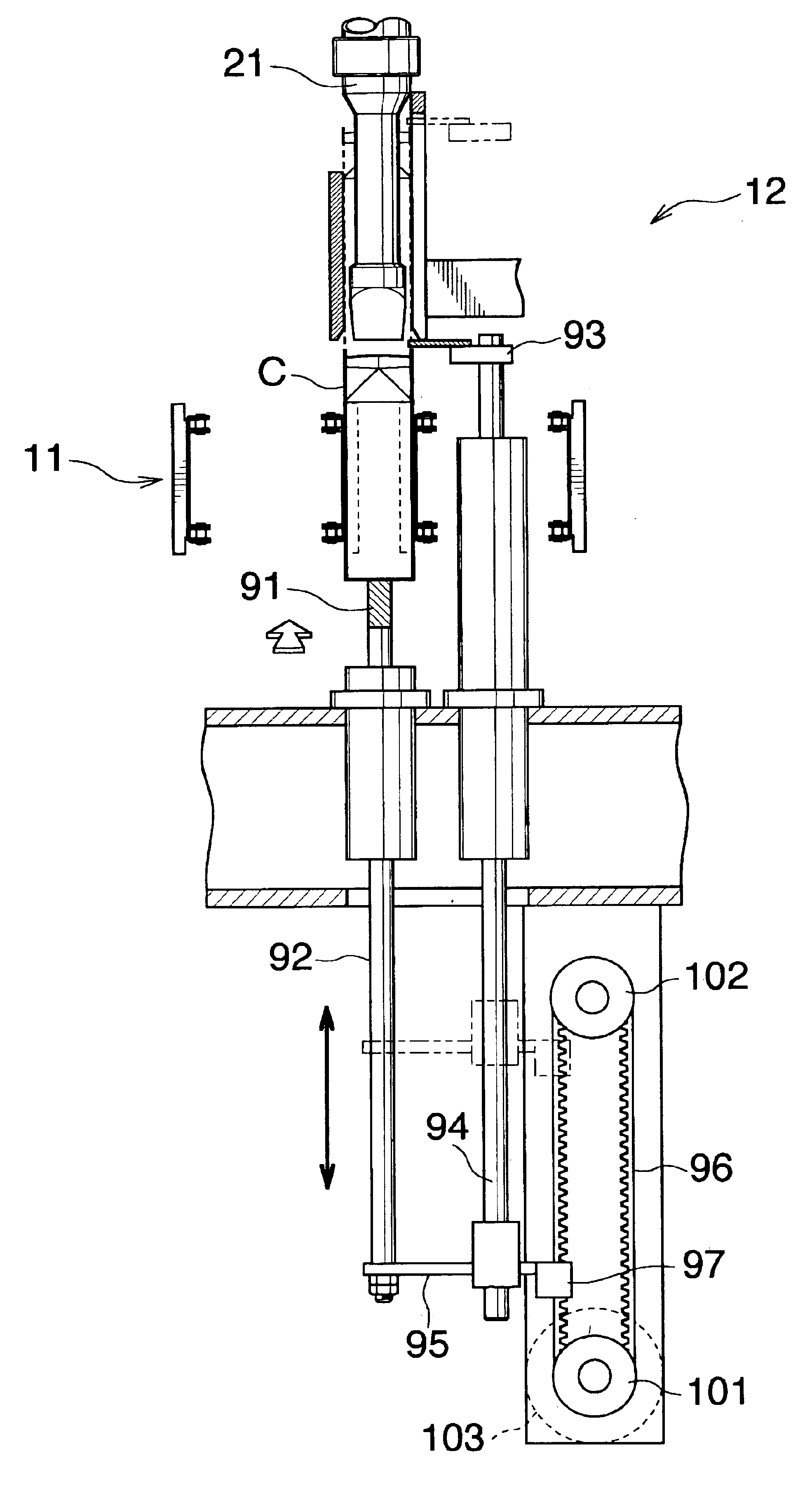
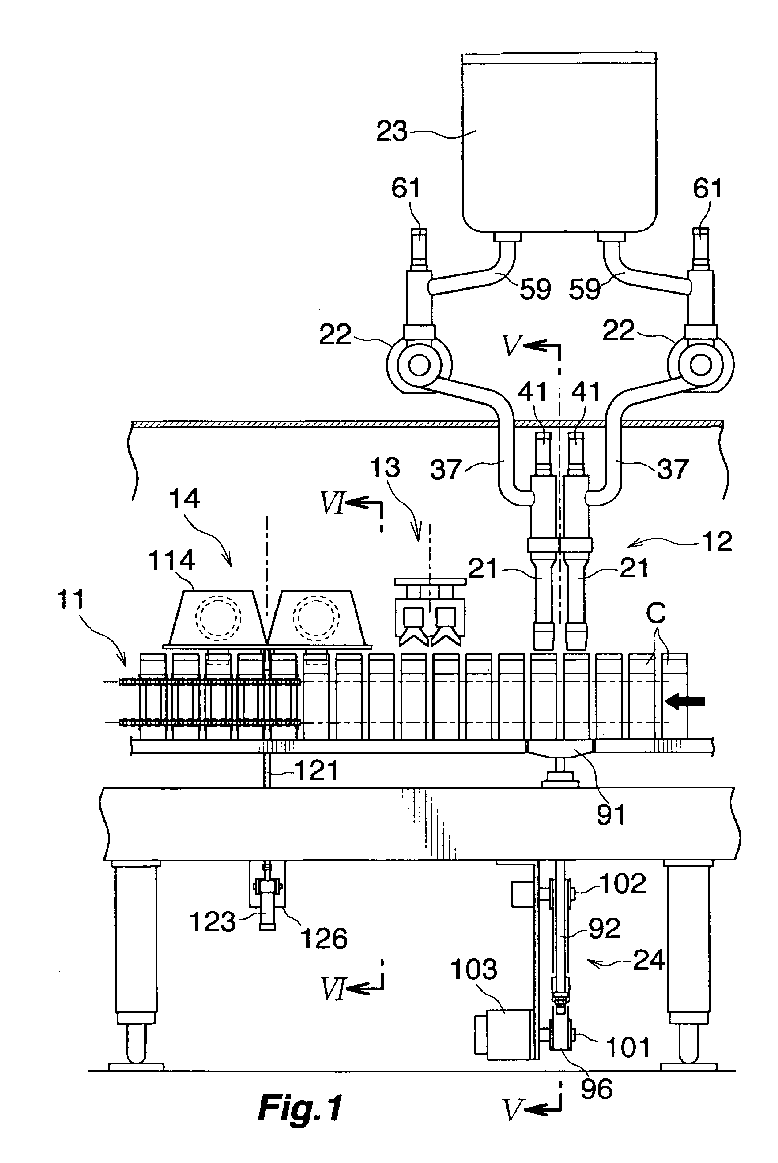
[0032]FIG. 1 shows a conveyor 11 for forwardly transporting containers C, having a bottom and rectangular to square in cross section, intermittently, two at a time, and a filling apparatus 12, top breaker 13 and top heater 14 which are arranged in this order from the rear forward along the path of transport by the conveyor.

[0033]The filling apparatus 12 and the top heater 14 are driven by the drive device of the invention in which a fluid pressure actuator is used.

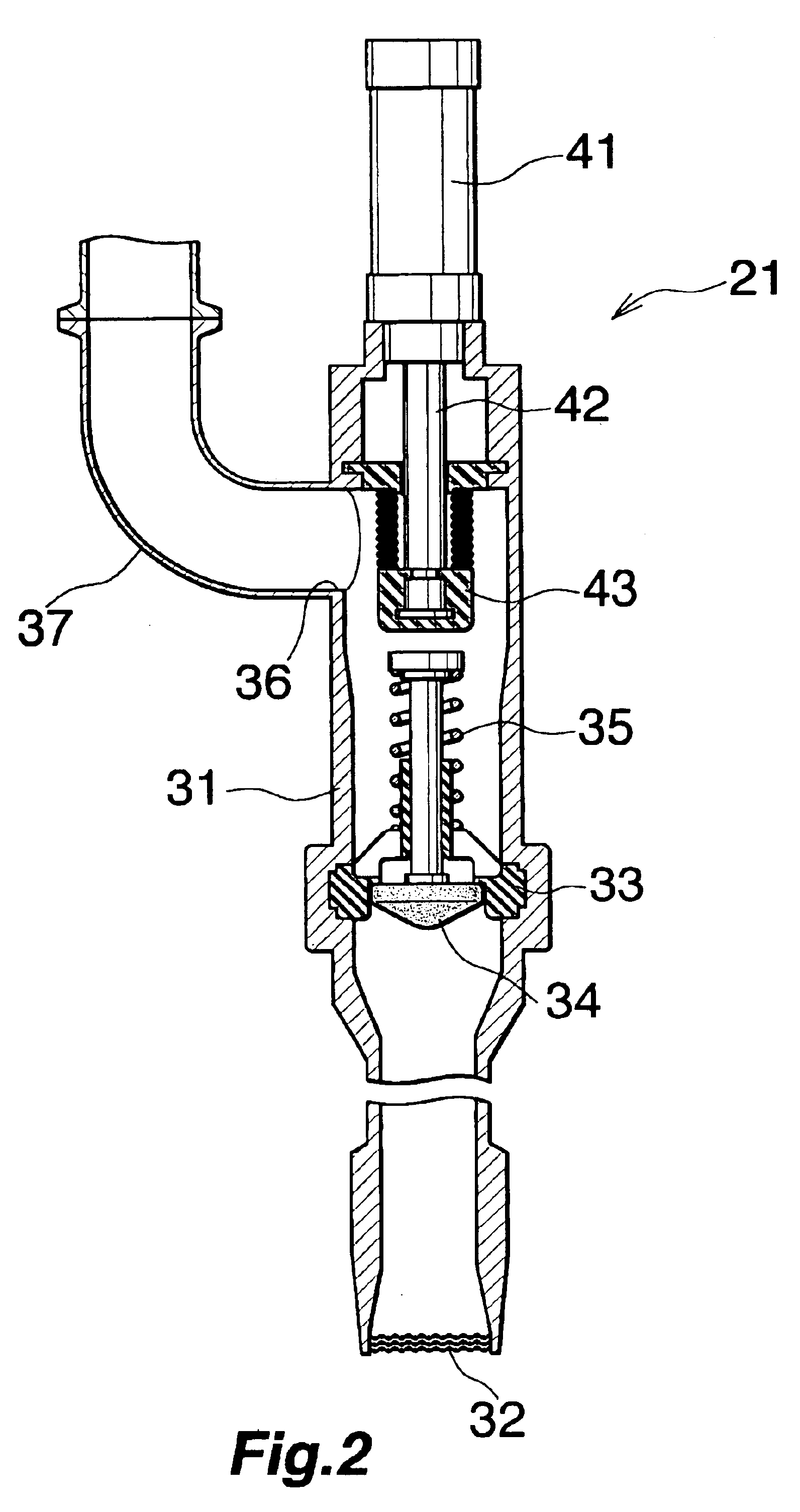
[0034]The filling apparatus 12 comprises two filling nozzles 21 arranged above the path of transport of containers in corresponding relation with the two contain...


PUM

PropertyMeasurementUnit
cycle velocityaaaaaaaaaa
pressureaaaaaaaaaa
flow rateaaaaaaaaaa

Abstract

A drive device comprises an air cylinder 123 for causing an operating member for a packaging operation to perform a reciprocating motion, a sensor 132 for detecting the cycle velocity or time of the air cylinder 123, a control valve 222 for controlling the pressure or flow rate of the fluid to be supplied to the air cylinder 123, and an a sequencer 201 for setting a reference value SV corresponding to the cycle velocity or time of the air cylinder 123, receiving a value PV detected by the sensor 132 as an input, calculating a valve opening degree so as to reduce the deviation of the detected value PV from the reference value SV to zero and setting the opening degree of the control valve 222 based on the calculated valve opening degree.

Description

BACKGROUND OF THE INVENTION[0001]The present invention relates to drive devices for use in packaging machines, for example, for intermittently transporting containers, filling contents into the containers during transport and sealing off the filled containers, the drive device being adapted to drive an operating member for the packaging operation.[0002]Already known as such drive devices are those comprising mechanical means such as a cam, those comprising a servo motor or like motor and those comprising a fluid pressure actuator such as an air cylinder.[0003]Drive devices wherein a cam or like mechanical means is used are suitable for causing an operating member to perform an accurate movement but have the problem of being complex in construction or requiring labor and time for altering the operation curve.[0004]Drive devices comprising a servo motor of like motor permit an accurate movement, are usable with an altered operation curve which is easy to prepare, and are therefore pla...

Claims


Application Information

Patent Timeline
Patent Type & Authority Patents(United States)
IPC IPC(8): B65B65/00F15B19/00B65B3/34B65B65/02F15B13/044F15B21/08
CPCB65B3/34B65B65/02F15B19/002F15B21/087
Inventor KONDO, MASAKATSUKAMIJI, TAKAYOSHIMATSUMOTO, KENJI
Owner SHIKOKU KAKOOKI CO LTD
Why Eureka
Try Eureka