Container base structure responsive to vacuum related forces

Active Publication Date: 2005-09-13
AMCOR RIGID PLASICS USA LLC
View PDF19 Cites 153 Cited by
  • Summary
  • Abstract
  • Description
  • Claims
  • Application Information

AI Technical Summary

Benefits of technology

[0015]Accordingly, this invention provides for a plastic container which maintains aesthetic and mechanical integrity during any subsequent handling after being hot filled and cooled to ambient having a base structure that allows for significant absorption of vacuum pressures by the base without unwanted deformation in other portions of the container. In a glass container, the container does not move, its structure must restra

Problems solved by technology

Pasteurization and retort both present an enormous challenge for manufactures of PET containers in that heat set containers cannot withstand the temperature and time demands required of pasteurization and retort.
On amorphous material, thermal processing of PET material results in a spherulitic morphology that interferes with the transmission of light.
In other words, the resulting crystalline material is opaque, and thus, generally undesirable.
This product shrinkage phenomenon results in the creation of a vacuum within the container.
If not controlled or otherwise accommodated, these vacuum pressures result in deformation of the container which leads to either an aesthetically unacceptable container or one which is unstable.
While vacuum panels have allowed the containers to withstand the rigors of a hot fill procedure

Method used


Image

  • Container base structure responsive to vacuum related forces
  • Container base structure responsive to vacuum related forces
  • Container base structure responsive to vacuum related forces

Examples


Embodiment Construction

[0024]The following description of the preferred embodiments is merely exemplary in nature, and is in no way intended to limit the invention or its application or uses.

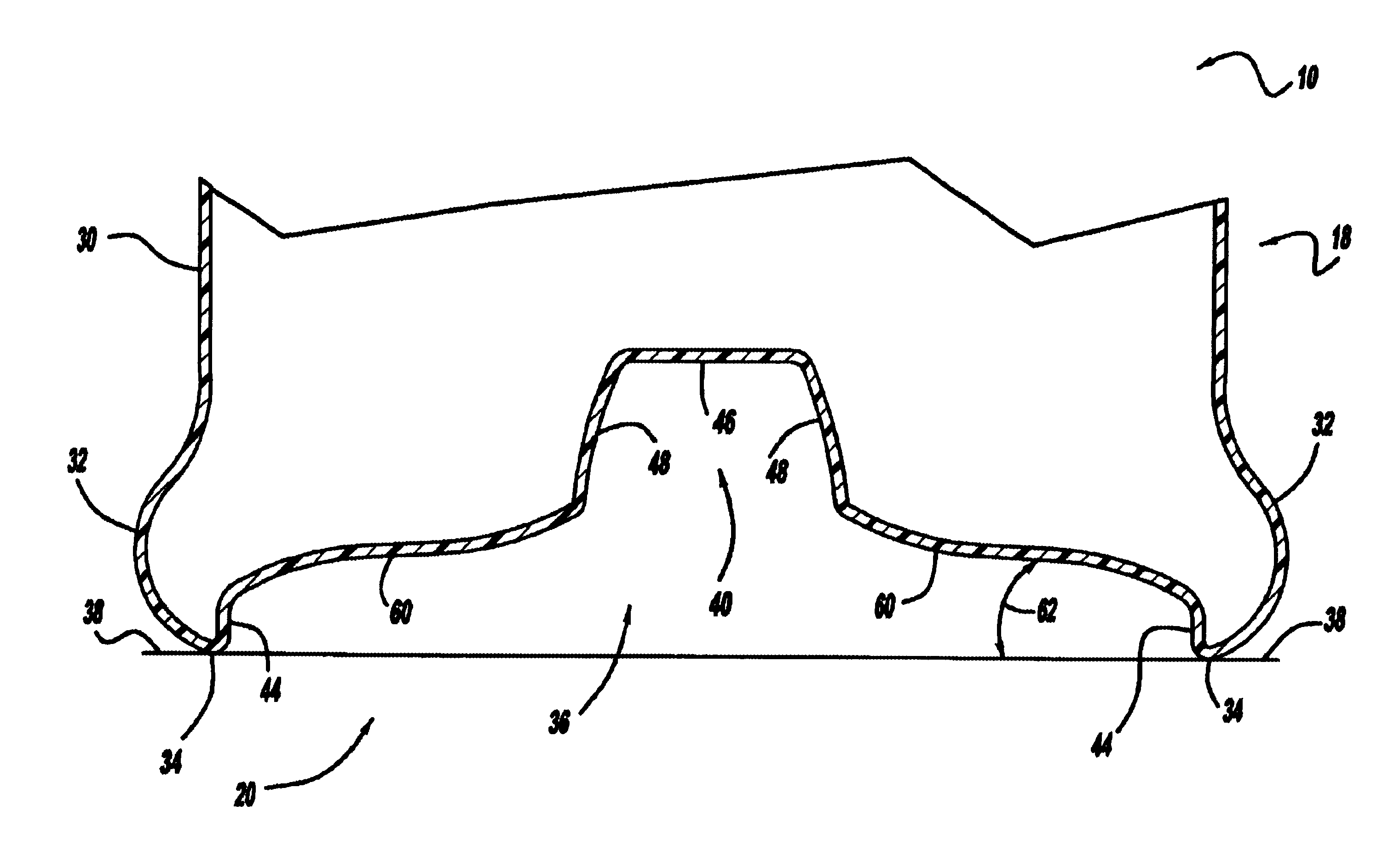
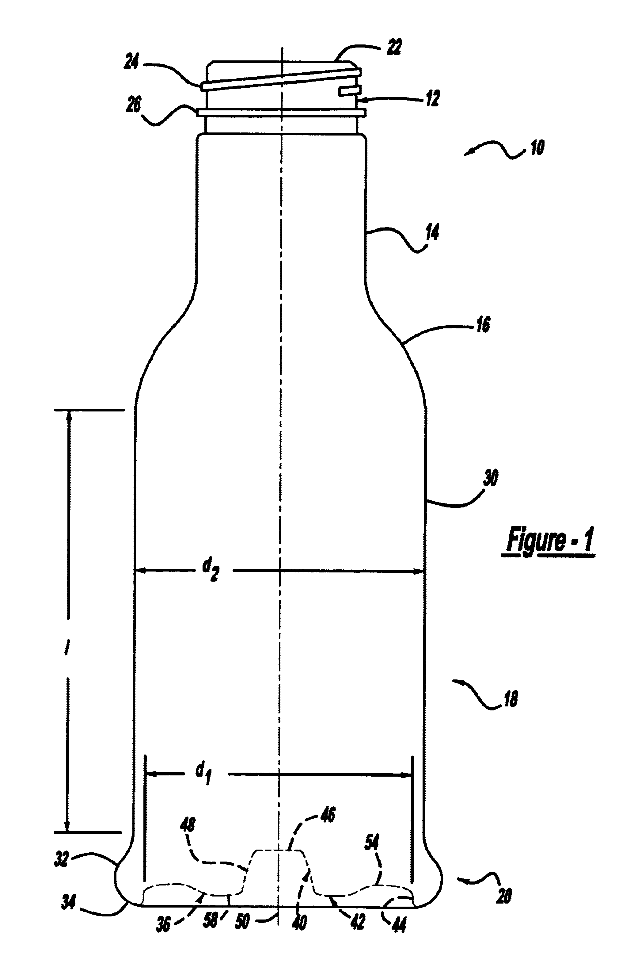
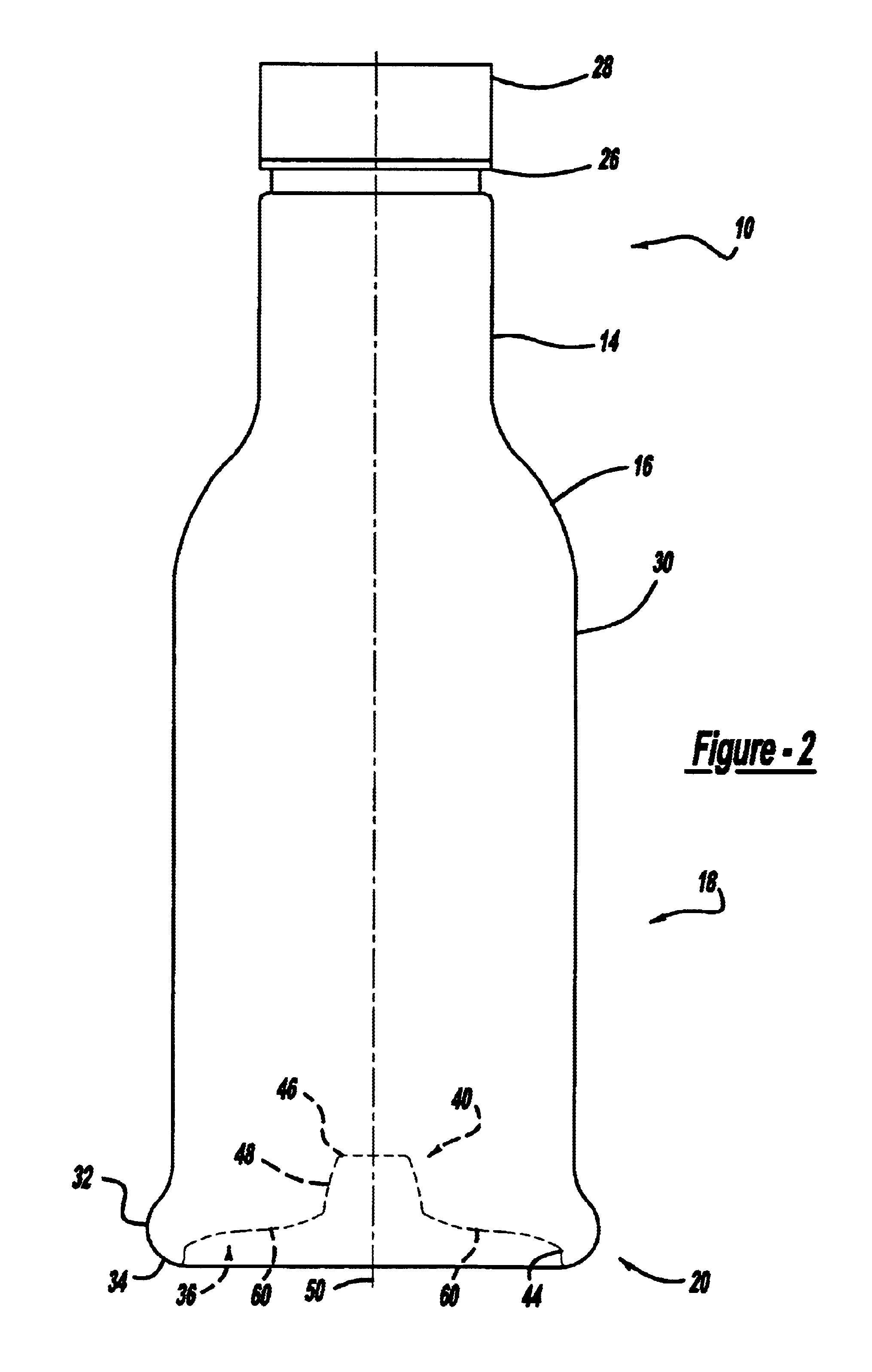
[0025]As discussed above, to accommodate vacuum forces during cooling of the contents within a heat set container, containers have been provided with a series of vacuum panels or pinch grips around their sidewalls. The vacuum panels and pinch grips deform inwardly under the influence of the vacuum forces and prevent unwanted distortion elsewhere in the container. However, with the vacuum panels and pinch grips, the container sidewall cannot be smooth or glass-like, an overlying label is not smooth, and end users can feel the vacuum panels and pinch grips when grasping and picking up the containers.

[0026]In a vacuum panel-less container, a combination of controlled deformation (e.g. in the base or closure) and vacuum resistance in the remainder of the container is required. Accordingly, this invention provides for a pl...


PUM


Abstract

A plastic container having a base portion adapted for vacuum pressure absorption. The base portion including a contact ring upon which the container is supported, an upstanding wall and a central portion. The upstanding wall being adjacent to and generally circumscribing the contact ring. The central portion being defined in at least part by a central pushup and an inversion ring which generally circumscribes the central pushup. The central pushup and the inversion ring being moveable to accommodate vacuum forces generated within the container.

Description

TECHNICAL FIELD OF THE INVENTION[0001]This invention generally relates to plastic containers for retaining a commodity, and in particular a liquid commodity. More specifically, this invention relates to a panel-less plastic container having a base structure that allows for significant absorption of vacuum pressures by the base without unwanted deformation in other portions of the container.BACKGROUND OF THE INVENTION[0002]Numerous commodities previously supplied in glass containers are now being supplied in plastic containers, more specifically polyester and even more specifically polyethylene terephthalate (PET) containers. Manufacturers and fillers, as well as consumers, have recognized that PET containers are lightweight, inexpensive, recyclable and manufacturable in large quantities.[0003]Manufacturers currently supply PET containers for various liquid commodities, such as beverages. Often these liquid products, such as juices and isotonics, are filled into the containers while ...

Claims


Application Information

Patent Timeline
IPC IPC(8): B65D79/00B65D1/02
CPCB65D1/0276B65D79/005B65D79/0081B65D1/02B65D79/00B65D1/14B65D1/00
Inventor LISCH, G. DAVIDSILVERS, KERRY W.VAILLIENCOURT, DWAYNE G.
Owner AMCOR RIGID PLASICS USA LLC
Why Eureka
Try Eureka