Sheet feeding apparatus

a feeding apparatus and sheet technology, applied in the direction of thin material processing, instruments, article separation, etc., can solve the problems of increasing power consumption, generating noise, paper jamming, etc., and achieve the effect of reliably feeding the sheets

Inactive Publication Date: 2005-09-13
KONICA CORP
View PDF4 Cites 13 Cited by
  • Summary
  • Abstract
  • Description
  • Claims
  • Application Information

AI Technical Summary

Benefits of technology

[0012]To solve the above-mentioned problems, the primary object of the present invention is to provide a simply-structured sheet feeding apparatus that blows air on the stacked sheets from the lateral side to the sheet feeding direction, thereby individually separating the sheets regardless of the size of the sheets and reliably feeding the sheets one by one.

Problems solved by technology

If this kind of sheet feeding apparatus feeds multiple sheets simultaneously, a paper jam may occur.
If the feeding force is not strong enough, misfeeding may occur.
Some types of paper adhere to one another when stacked that it is difficult for the above-mentioned sheet feeding apparatus to prevent two or more sheets from being fed simultaneously.
However, the suction method requires a compressor that can produce high suction, which results in large-scale equipment which increases power consumption and generates noise.
However, there is a problem with this method in that when the stacked sheets 100 are large, as shown in FIG. 5, several top sheets 100b of the stacked sheets 100 located in front of the air outlet 1 are lifted as a group.
This prevents the sheet feeding roller from coming in complete contact with the sheets, resulting in misfeeding.
However, the position of the uppermost surface of the paper stack constantly changes in the vertical direction, consequently, it becomes impossible to reliably detect the position of the uppermost surface of the paper stack.
Moreover, when a hold-down member 3 is provided at the rear end of the stacked sheets 100, the location of the hold-down member 3 has to be changed according to different sizes of the sheets 100, thereby making the structure of the sheet feeding apparatus complicated.

Method used


Image

  • Sheet feeding apparatus
  • Sheet feeding apparatus
  • Sheet feeding apparatus

Examples


Embodiment Construction

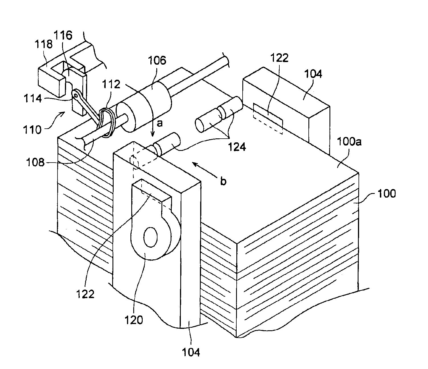
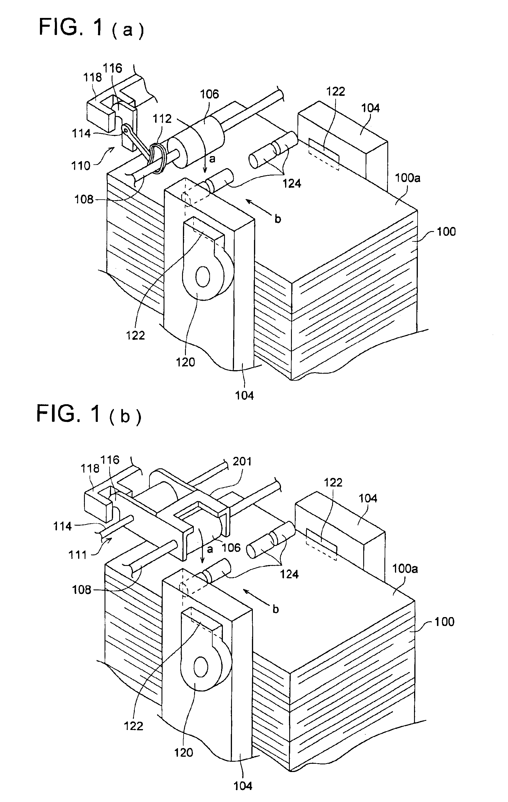
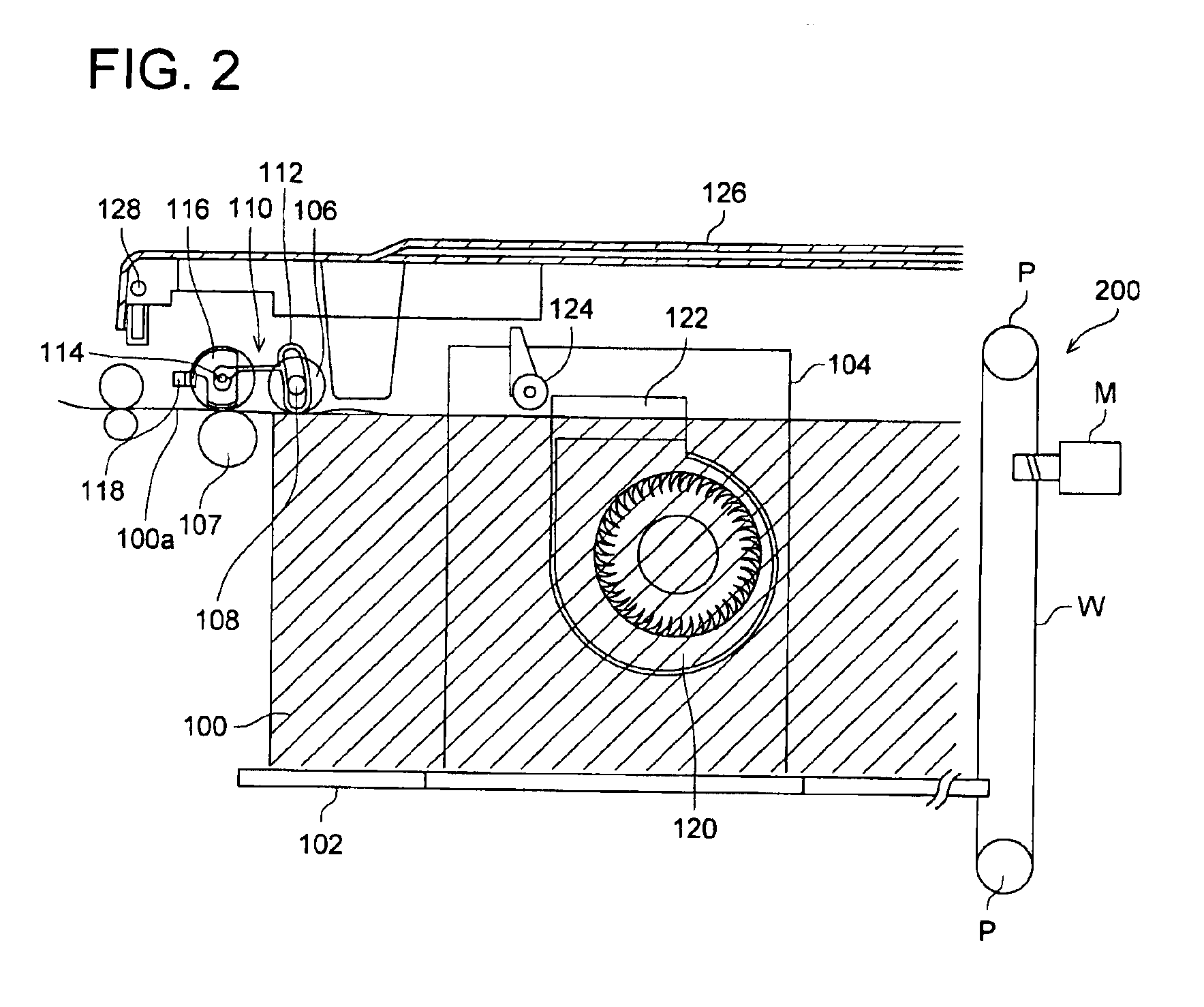
[0022]An embodiment of the present invention will be described hereinafter in reference to the drawings. FIGS. 1(a) and 1(b) are perspective views of the main part of a sheet feeding apparatus according to the present invention with its cover removed. FIG. 1(a) shows a view indicating a sheet surface sensor 110, while FIG. 1(b) shows a view indicating an another sheet surface sensor 111. FIG. 2 is a longitudinal sectional view of the main part of the sheet feeding apparatus. FIG. 3 is a top view of the main part shown in FIG. 1.

[0023]In these drawings, a stack of sheets 100 is placed on a tray 102 which has an elevation mechanism 200, as shown in FIG. 2, that raises and lowers the tray. Lateral adjusting members 104, such as side panels, etc., move freely in the direction that intersects with the feeding direction of the stacked sheets 100, that is, the width direction in this embodiment, and slightly come in contact with both lateral sides of the stacked sheets 100 to restrict the ...


PUM


Abstract

A sheet feeding apparatus includes a sheet feeding roller that comes in contact with stacked sheets and feeds sheets one by one from the top, wherein an air outlet is provided so that air can be blown onto the upper part of the stacked sheets from the lateral side in the sheet feeding direction, and a floatation suppression member for suppressing floatation of the sheet is provided between the air outlet and the feeding roller and spaced apart from the uppermost surface of the stacked sheets.

Description

CROSS-REFERENCE TO RELATED APPLICATIONS[0001]This is a Continuation of U.S. patent application Ser. No. 10 / 225,380, filed Aug. 21, 2002, now U.S. Pat. No. 6,729,614.BACKGROUND OF THE INVENTION[0002]The present invention relates to a sheet feeding apparatus used in copy machines, printers, printing machines, etc. and more specifically to a sheet feeding apparatus capable of separately feeding various types of sheets such as transparent sheets, scored papers, etc.[0003]Copy machines, printers, and printing machines are equipped with a sheet feeding apparatus that feeds sheets one by one from a stack of copy paper by means of a sheet feeding roller. If this kind of sheet feeding apparatus feeds multiple sheets simultaneously, a paper jam may occur. If the feeding force is not strong enough, misfeeding may occur. To avoid these problems, there are methods to ensure that sheets are fed one by one. That is, increasing the friction coefficient between the sheet feeding roller and the sheet...

Claims


Application Information

Patent Timeline
Patent Type & Authority Patents(United States)
IPC IPC(8): B65H1/18B65H1/08B65H3/06B65H3/48B65H3/54G03G15/00B65H1/04B65H1/26B65H3/66B65H7/14
CPCB65H1/18B65H3/06B65H3/48B65H3/54
Inventor OKAZAKI, SHIGERUUEDA, DAISUKEKATO, KENJI
Owner KONICA CORP
Why Eureka
Try Eureka