
Seal arrangement

Inactive Publication Date: 2005-09-13
TOYODA GOSEI METEOR GMBH
View PDF21 Cites 31 Cited by
  • Summary
  • Abstract
  • Description
  • Claims
  • Application Information

AI Technical Summary

Benefits of technology

[0007]The sealing region is preferably tubular in formation. The latching connection of the latching regions and the counter latching regions together ensures that the profile is held securely on the grip rail even during heavy duty operation. When the profile is damaged, it is then possible to release these latching connections with a small amount of effort and latch a new profile to the grip rail which remains in place. Initially, the grip rail can be fixed to one of the components and then the pro file can be latched to the grip rail. However, it is also possible initially to latch the profile and the grip rail together and subsequenty to fix this preassembled subassembly to one of the components. By virtue of the fact that a first and a second latching region are provided on longitudinal edges of the grip rail, wherein a first latching region is formed along an outer longitudinal edge of the grip rail, this provides a particularly large base for mounting the profile on the grip rail and ensures that the profile is held correspondingly securely. The first sealing lip according to the invention serves to provide a perfect lateral termination of the holding region and an effective seal with respect to the first component which supports the sealing arrangement. In a similar manner, the second sealing lip according to the invention serves to provide a visually pleasing and in particular sealed outer termination of the lo profile with respect to the first component.
[0014]Extruding the grip rail and attaching the clips to it is particularly advantageous, if the installation situation for the grip rail has a three-dimensional progression. It is then possible in the old tool to give the grip rail this three-dimensional shape and to ensure that the grip rail can be attached to the first component without becoming jammed.

Problems solved by technology

During operation, this can lead to visually unfavorable gaps and progressions of the profile seal.
By virtue of the fact that a particular U-shaped locking part is required to form a T-shaped groove, this produces in mechanical terms a relatively complicated attachment of the sealing profile to the grip rail.
In dependence upon the material formation of these parts, this can also give rise to disadvantages for the endurance of sealing effect.

Method used


Image

  • Seal arrangement
  • Seal arrangement
  • Seal arrangement

Examples


Embodiment Construction

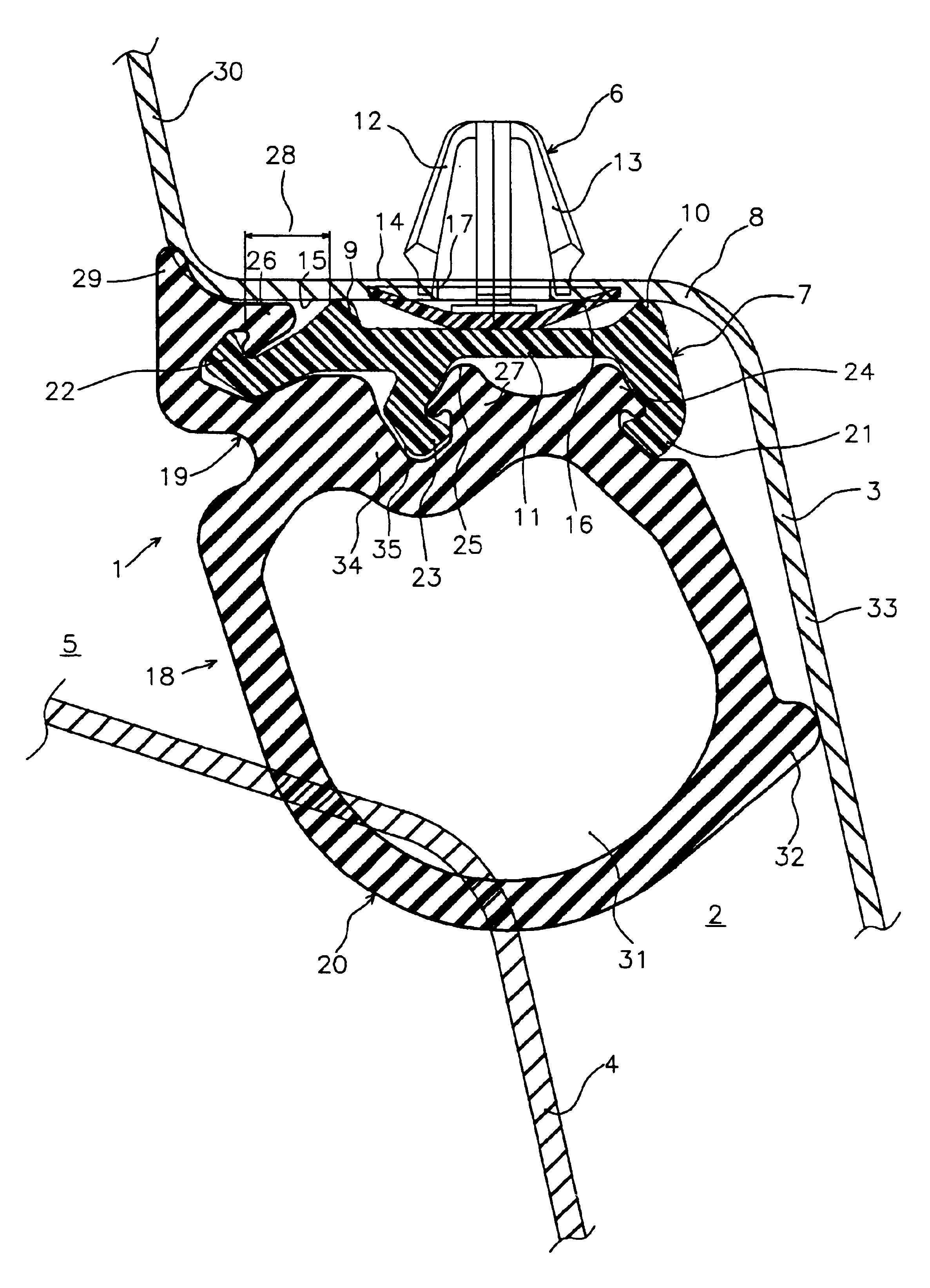
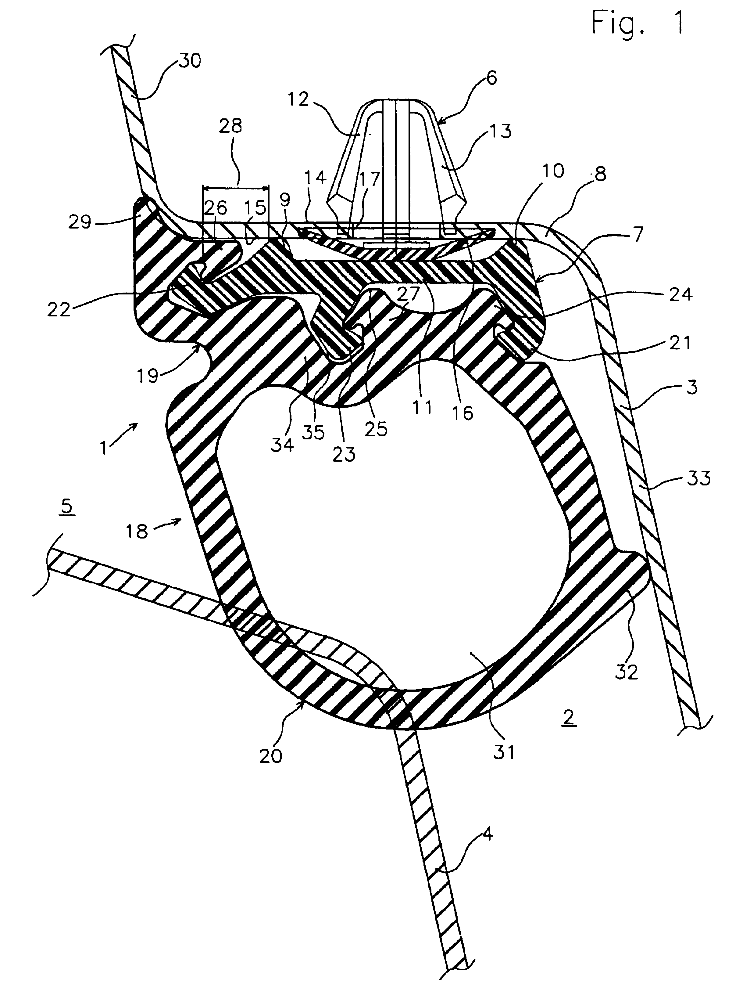
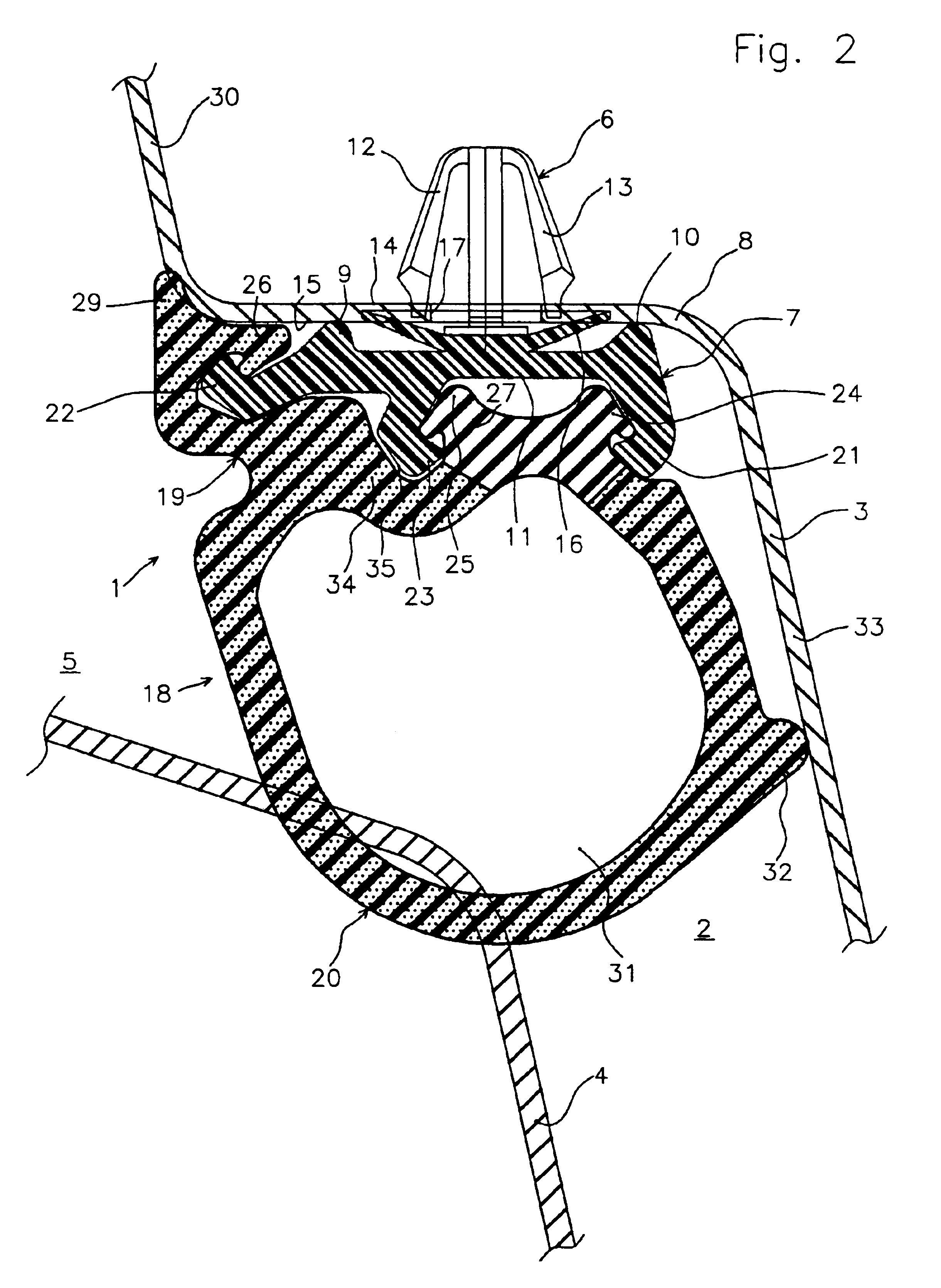
[0022]FIG. 1 shows a sealing arrangement 1 for a gap 2 between a first component 3 and a second component 4. The first component 3 is a closing element, such as e.g. a door or a hinged lid of a motor vehicle. The second component 4 is formed in FIG. 1 by an edge of an opening 5 of a motor vehicle which is to be closed, wherein the edge is a component of a sill of the motor vehicle. The sealing arrangement 1 is not only able to extend along the base of the door 3, as shown in FIG. 1, but can also extend right around the opening 5.

[0023]A grip rail 7 is fixed to the first component 3 by means of mutually spaced apart clips 6. Since a lower connection plate 8 of the first component 3 extends substantially linearly, the grip rail 7 can be formed in a two-dimensional manner and can be extruded from synthetic material. Suitable synthetic materials are e.g. polyoxy methylene (POM), polyamide (PA) or a thermoplastic elastomer (TPE) with a Shore D hardness of 40 to 80.

[0024]Support ribs 9 an...


PUM


Abstract

A seal to seal a gap between two cooperating components is disclosed. The seal includes a grip rail attachable to the first component. The grip rail has opposite edge portions to which multiple latching regions are attached. A base having opposite sides is positioned adjacent to the grip rail. Multiple counter latching regions that engage with the latching regions are positioned along one side of the base. A sealing profile adapted to engage the second component is mounted on the other side of the base. A first sealing lip is formed along one counter latching region, and a second sealing lip is formed on the sealing profile. Both sealing lips project outwardly for engagement with the first component.

Description

FIELD OF THE INVENTION[0001]The invention relates to a sealing arrangement for a gap between two cooperating components, for example, a door or a hinged lid of a motor vehicle, and an edge of an opening which is to be closed.BACKGROUND OF THE INVENTION[0002]German and French patent documents DE 198 03 445, FR 2 520 467, DE 295 13 597 and DE 297 20 053 disclose comparable sealing arrangements which are intended to seal the gap between on the one hand a closing element, which can be moved relatively to an opening in a motor vehicle, and on the other hand the inner-side edge region of the opening which faces said dosing element. They generally consist of a holding portion, which is adapted for attachment either to the inner edge region of the opening or to the outer-side edge region of the closing element, and of a sealing profile which is integrally formed on said holding portion and which in the closed state of the closing element lies in a sealing manner under resilient deformation ...

Claims


Application Information

Patent Timeline
IPC IPC(8): B60J10/00B60J10/08F16J15/06F16J15/02F16J15/32B60J10/16B60J10/235B60J10/24B60J10/30B60J10/80
CPCB60J10/0005B60J10/0022B60J10/0031B60J10/0062B60J10/08F16J15/027F16J15/061Y10S277/921B60J10/16B60J10/235B60J10/24B60J10/30B60J10/80
Inventor GENTEMANN, MARTINKOCH, MICHAEL
Owner TOYODA GOSEI METEOR GMBH
Learn More