

Ink-jet printing method and apparatus
a technology of inkjet printing and inkjet printing, applied in the field of inkjet printing methods and apparatuses, can solve the problems of increasing image data, deteriorating image quality, and resultant streaks, and achieves the effect of sufficiently suppressing density irregularities and streaks, and high-quality images
- Summary
- Abstract
- Description
- Claims
- Application Information
AI Technical Summary
Benefits of technology
Problems solved by technology
Method used
Image

Examples
first embodiment
[First Embodiment]
[0088]This embodiment exemplifies a case wherein multilevel image data having each pixel expressed by 2 bits is printed to reproduce tones at a resolution of 600×600 dpi and expressing each pixel by a combination of a plurality of dots at different landing positions.
[0089]FIG. 8 is a view for explaining the correspondence between the quantization levels (gray levels) and the pixel patterns in this embodiment. As shown in FIG. 8, in this embodiment, each pixel is expressed by one of pixel patters (A) to (D) each constituted by four kinds of dots within a 2×2 matrix. Therefore, the amount of data stored as image information in a memory such as the RAM 702 in advance is 2 bits. Multilevel input image data is quantized into four-valued (level) data and converted into image data formed from four kinds of pixel patterns corresponding to the quantization levels as indicated by “(A)” to “(D)” in FIG. 8. The pixel pattern (A) is a pattern without any dot; the pixel pattern ...
second embodiment
[Second Embodiment]
[0107]The second embodiment of the present invention will be described below. In the following description, a description of the same part as that in the first embodiment will be omitted, and a particular emphasis is placed on a characteristic feature of this embodiment.
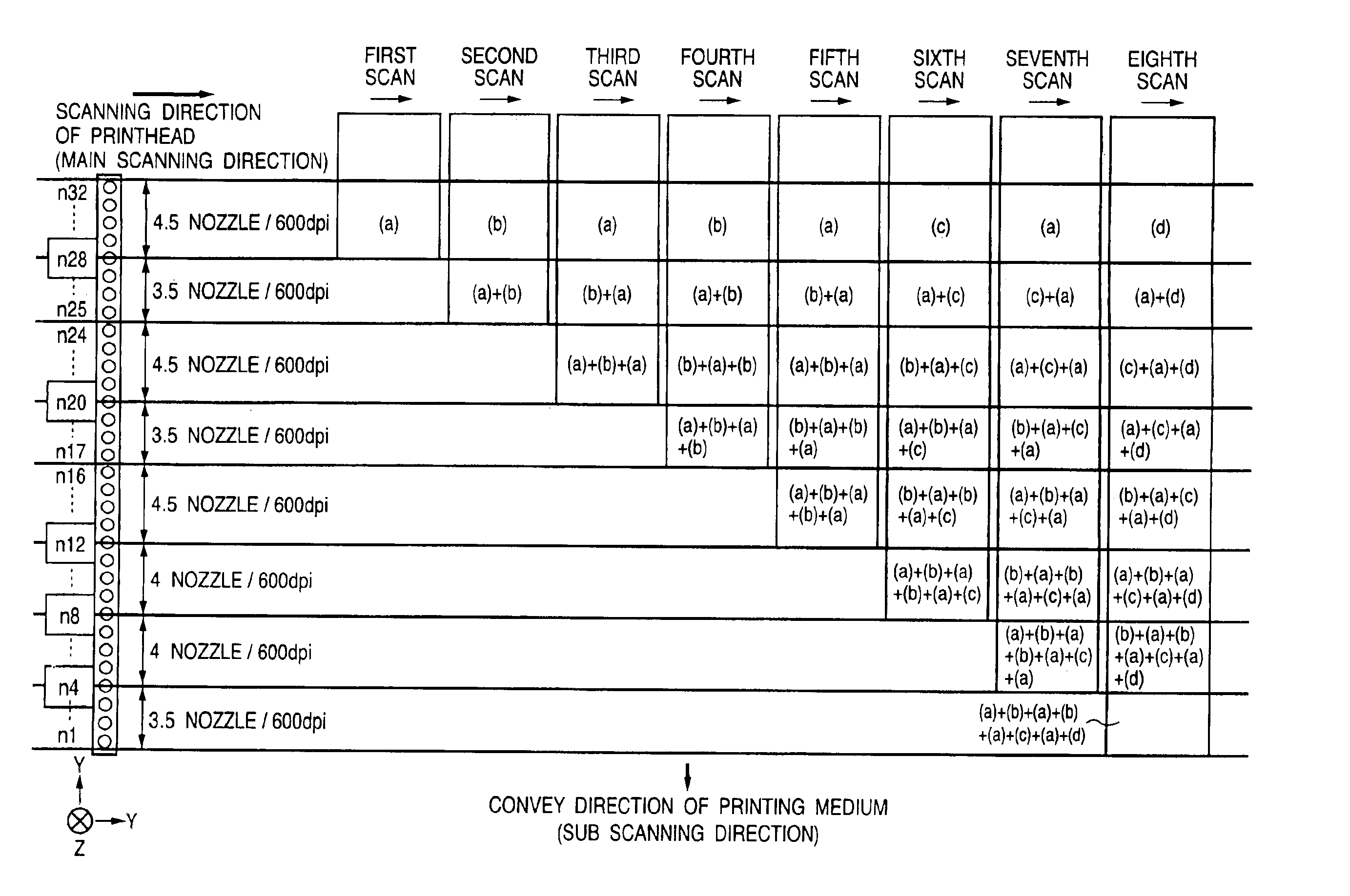
[0108]In this embodiment, in the scheme of printing multilevel image data having each pixel expressed by 2 bits to reproduce tones at a resolution of 600×600 dpi by expressing each pixel using a combination of a plurality of dots at different landing positions, the scanning direction in which data with a low quantization level (gray level) is completed is made to differ from the scanning direction in which only data with a high quantization level is completed.
[0109]Assume that quantized pixel patterns in the second embodiment are the same as those shown in FIG. 8 which are used in the first embodiment, and the same mask patterns as those shown in FIG. 9 which are used in the first embodiment are us...
third embodiment
[Third Embodiment]
[0118]The third embodiment of the present invention will be described below. In the following description, a description of the same part as that in the first and second embodiments will be omitted, and a particular emphasis is placed on a characteristic feature of this embodiment.
[0119]In this embodiment, in the scheme of printing multilevel image data having each pixel expressed by 2 bits to reproduce tones at a resolution of 600×600 dpi by expressing each pixel using a combination of a plurality of dots at different landing positions, different pixel patterns are provided for the same quantization level (gray level).
[0120]FIG. 12 is a view for explaining the correspondence between the quantization levels (gray levels) and the pixel patterns in this embodiment. As shown in FIG. 12,
[0121]in this embodiment, each pixel is expressed by one of pixel patters (A) to (E) each constituted by four kinds of dots within a 2×2 matrix. Therefore, the amount of data stored as ...
PUM
 Abstract
Description
Claims
Application Information