Supercharge Your Innovation With Domain-Expert AI Agents!

Ink cartridge

Inactive Publication Date: 2005-09-13
BROTHER KOGYO KK
View PDF25 Cites 19 Cited by
  • Summary
  • Abstract
  • Description
  • Claims
  • Application Information

AI Technical Summary

Benefits of technology

[0012]With this configuration, the ink can be supplied to the ink reservoir easily through the hollow needle. After the ink supply is completed, the valve structure is closed so that the ink does not flow from the ink reservoir to the opening and / or bubbles of the air and impurities do not enter from the opening to the ink reservoir. It should be noted that the stop also has a sealing effect to block the communication between both sides thereof.
[0021]Preferably, the protrusion is formed to be slightly larger than a portion of the fluid path where the protrusion is fitted in, and the protrusion is compressed when fitted in the fluid path. Generally, when the protrusion is compressed, it is hardened. Thus, the above configuration improves the sealing effect.

Problems solved by technology

If air or impurities invade inside the reservoir, bubbles of the air and / or the impurities are supplied to the device together with the ink, which may cause trouble.
The impurities supplied to the printer may block up the ink nozzles.

Method used


Image

  • Ink cartridge
  • Ink cartridge
  • Ink cartridge

Examples


second embodiment

[0167

[0168]FIGS. 14A through 14D show a structure of the openings 7a and 7b, and the stops 6a and 6b, according to a second embodiment.

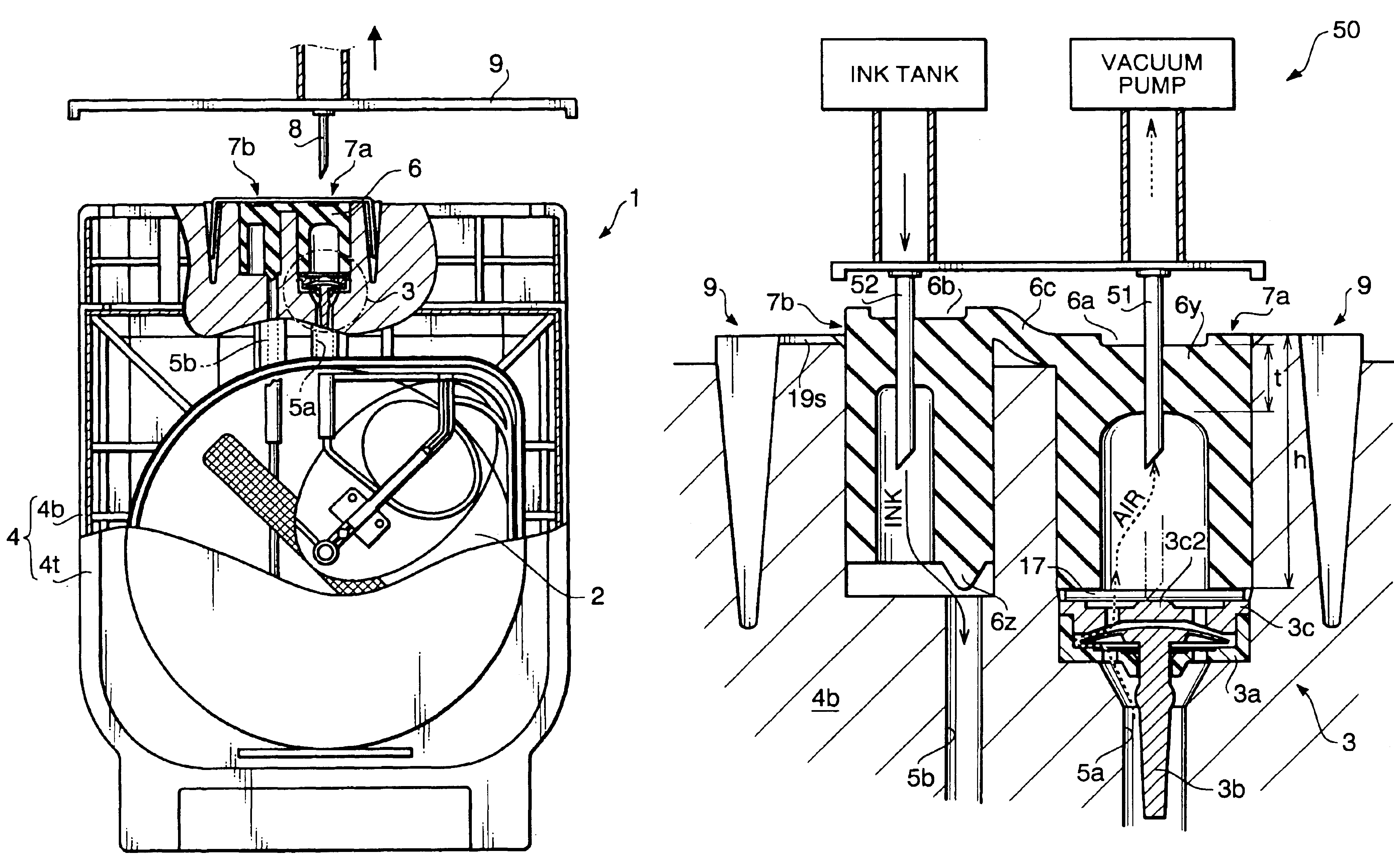
[0169]According to the second embodiment, as shown in FIG. 14A, the second stop 6b is provided with a protrusion 6z′ having a substantially cylindrical shape, which is different from the conical shape of the protrusion 6z shown in FIG. 8. Further, the protrusion 6z′ is provided at the central portion of the bottom surface of the second stop 6b. Corresponding to the location of the protrusion 6z′, the second path 5b communicates with the second opening 7b at the central portion of the bottom surface of the opening 7b.

[0170]FIG. 14B shows an ink filling operation according to the second embodiment. Similarly to the first embodiment, when the ink filling operation is performed, the second stop 6b is not completely inserted In the second opening 7b, and the protrusion 6z′ is spaced from the second path 5b so that the second path 5b communicates with the...

third embodiment

[0174

[0175]FIGS. 15A through 15D show a structure of the openings 7a and 7b, and the stops 6a and 6b, according to a second embodiment. The third embodiment is similar to the second embodiment except that an incision is formed on the protrusion 6z′ at its proximal end (i.e., the second stop 6b side end), and a curved second path 5b′ is provided instead of the straight second path 5b, as shown in FIG. 15A.

[0176]FIG. 15B shows an ink filling operation according to the third embodiment. Similarly to the first embodiment, when the ink filling operation is performed, the second stop 6b is not completely inserted in the second opening 7b, and the protrusion 6z′ is spaced from the second path 5b′ so that the second path 5b′ communicates with the second opening 7b. Therefore, the ink can be supplied from the second opening 7b to the ink reservoir 2 through the second path 5b′.

[0177]After the ink is filled, the second stop 6b is fully inserted in the second opening 7b as shown in FIGS. 15C ...

fourth embodiment

[0182

[0183]FIGS. 16A through 16D show a structure of the openings 7a and 7b, and the stops 6a and 6b, according to a fourth embodiment. According to the fourth embodiment, as shown in FIG. 16A, the second stop 6b is not provided with a protrusion, and a second path 5b″ is configured to communicate with the second opening 7b at the side surface thereof. The second path 5b″ has a curved shape and connects the second opening 7b and the ink reservoir 2. In the fourth embodiment, the side surface of the second stop 6b functions as a valve to close the second path 5b″.

[0184]FIG. 16B shows an ink filling operation according to the fourth embodiment. Similarly to the first embodiment, when the ink filling operation is performed, the second stop 6b is not completely inserted in the second opening 7b, and the second path 5b″ communicates with the second opening 7b. Therefore, the ink can be supplied from the second opening 7b to the ink reservoir 2 through the second path 5b″.

[0185]After th...


PUM


Abstract

An ink cartridge is provided with a housing defining a body of the cartridge, an ink reservoir accommodated in the housing, an opening formed on the housing. The opening communicates with the ink reservoir through a fluid path. The cartridge further includes a stop to be tightly fitted in the opening. The stop has an elasticity, and is configured such that a hollow needle can be penetrated therethrough. A hole formed on the stop by penetration of the hollow needle is closed by the elasticity of the stop after removal of the same. A valve structure is provided to a part of the stop, the valve structure selectively opens and closes the communication between the opening and the ink reservoir through the fluid path.

Description

[0001]This is a Divisional of application Ser. No. 10 / 256,067 filed Sep. 27, 2002, now U.S. Pat. No. 6,802,601. The entire disclosure of the prior applications is hereby incorporated by reference herein in its entirety.BACKGROUND OF THE INVENTION[0002]The present invention relates to an ink cartridge to be coupled to a device using ink.[0003]Conventionally, ink cartridges have been widely used in devices using ink. An example of such devices, an inkjet printing device has been known. The inkjet printing device typically includes an inkjet head, which has an ink nozzle. The ink nozzle is driven to eject ink drops toward recording medium such as a piece of paper to form images and characters thereon. Typically, the ink cartridge includes an ink reservoir, and the ink accommodated in the reservoir is supplied to the inkjet head.[0004]The exchangeable ink cartridge is advantageous in that when the printer runs out of the ink, only by replacing the old cartridge with a new cartridge. The...

Claims


Application Information

Patent Timeline
IPC IPC(8): B41J2/175
CPCB41J2/175B41J2/17503B41J2/17506B41J2/17513B41J2/1752B41J2/17523B41J2/17553B41J2/17566B41J2/17596B41J2002/14403
Inventor SUZUKI, TSUYOSHISASAKI, TOYONORI
Owner BROTHER KOGYO KK
Features
  • R&D
  • Intellectual Property
  • Life Sciences
  • Materials
  • Tech Scout
  • Unparalleled Data Quality
  • Higher Quality Content
  • 60% Fewer Hallucinations
Learn More