Stem of artificial hip joint

a hip joint and stem technology, applied in the field of stem of artificial hip joint, can solve the problems of increasing the time period of operation, affecting the operation, and leaking of toxic decomposition product,

Inactive Publication Date: 2005-09-13
KOSHINO TOMIHISA
View PDF17 Cites 17 Cited by
  • Summary
  • Abstract
  • Description
  • Claims
  • Application Information

AI Technical Summary

Benefits of technology

[0008]It is an object of the present invention to provide a stem of an artificial hip joint that can remove a gap when the stem is fixed to a femur even if the gap is formed between a proximal portion of the femur and a backside of the stem.
[0009]It is another object of the present invention to provide a stem of a hip joint, which can attain a sufficient bonding of a femur and the stem without using a considerable amount of bone cement.
[0010]According to the present invention for achieving the above objects, there is provided a stem of an artificial hip joint, the stem having an upper end portion to face a proximal side and a backside to face a greater trochanter and being adapted for insertion into, and fixation to, a medullary space of a femur to be fixed, the stem having a through bore opened both to said upper end portion and the vicinity of proximal end of said backside. The through bore is used as an inlet for injecting bone cement, so that the gap between the backside of the stem and the proximal portion of the femur can be filled with the bone cement.

Problems solved by technology

In the method using the bone cement 35, a considerable amount of the bone cement 35 is used, so that not only serious complications such as fat embolism, etc., are caused, but also the amount of a toxic decomposition product leaked from the cement 35 increases and may damage the bone.
Furthermore, curing of the bone cement takes a time, so that the time period of the operation increases.
Further, since no bone cement 35 is used, it takes several months to obtain a sufficient bonding of the femur 30 and the stem 10 to each other by bone growth, so that aftercare takes a long time.

Method used


Image

  • Stem of artificial hip joint
  • Stem of artificial hip joint
  • Stem of artificial hip joint

Examples


Embodiment Construction

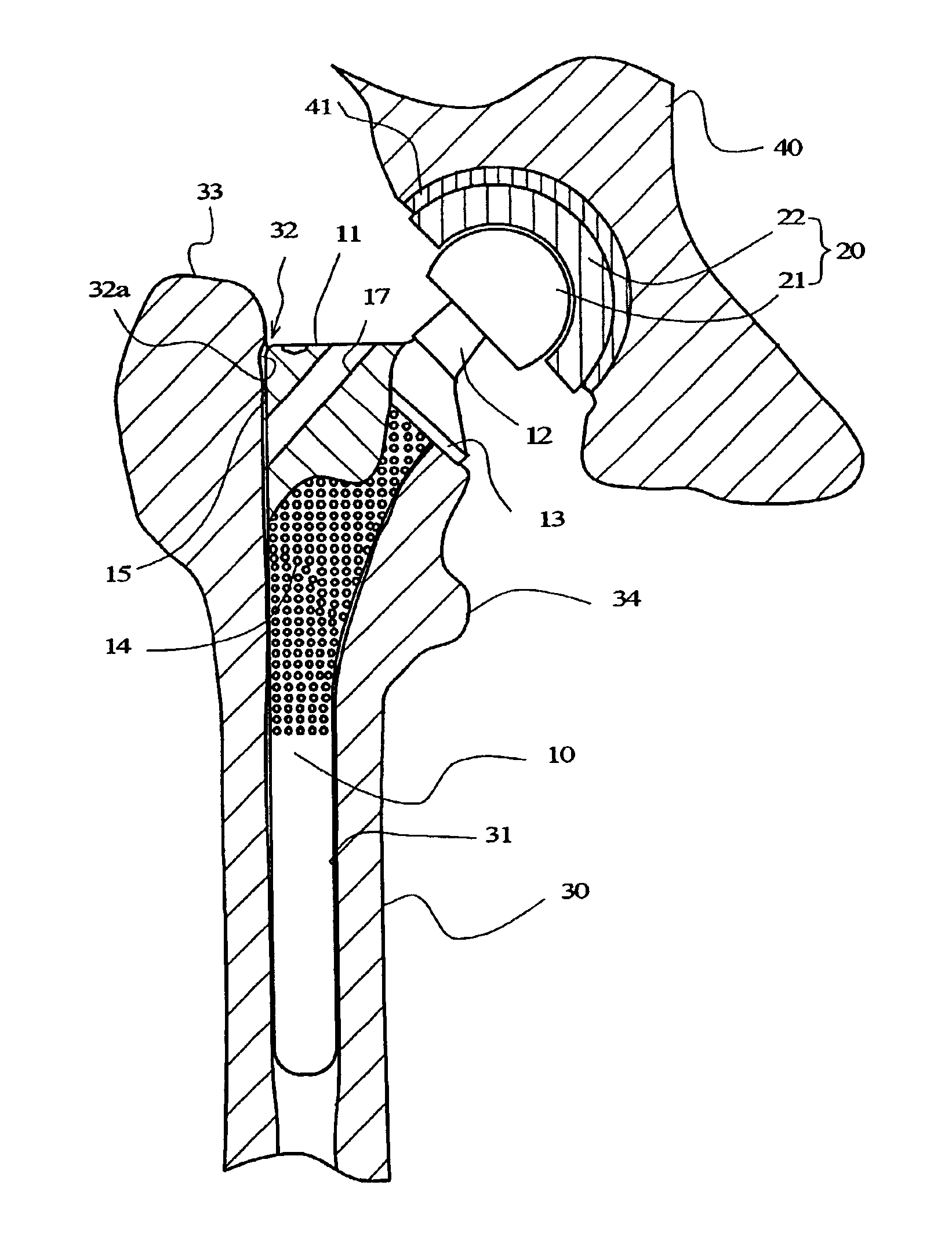
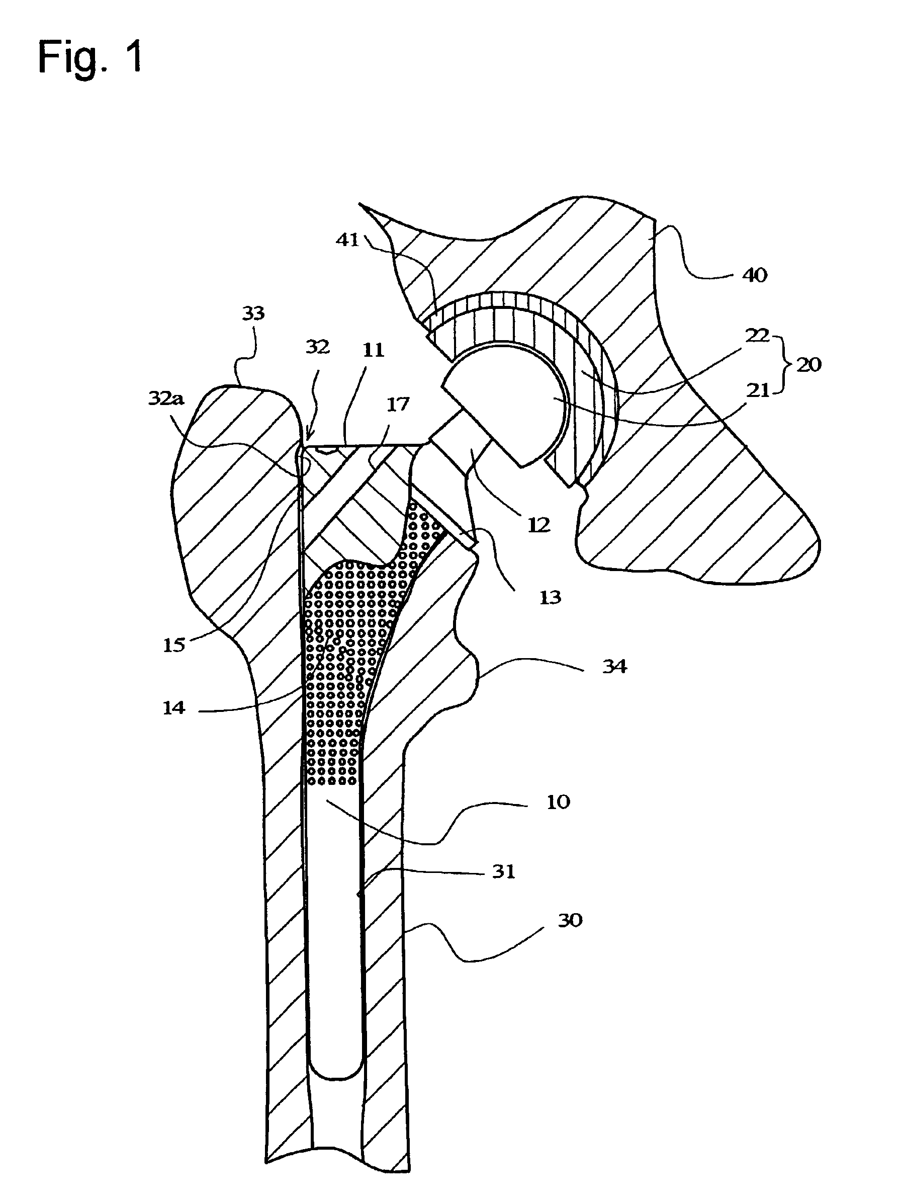
[0021]The stem of an artificial hip joint according to the present invention will be explained with reference to FIGS. 1 to 4 hereinafter.

[0022]The artificial hip joint has a stem 10 and a head 20. The stem 10 is insertable into the medullary space 31 of a femur 30 to be fixed. The head 20 is constituted of a ball 21 and a socket 22, and the socket 22 is to be fixed to the cotyle 41 of a pelvis 40.

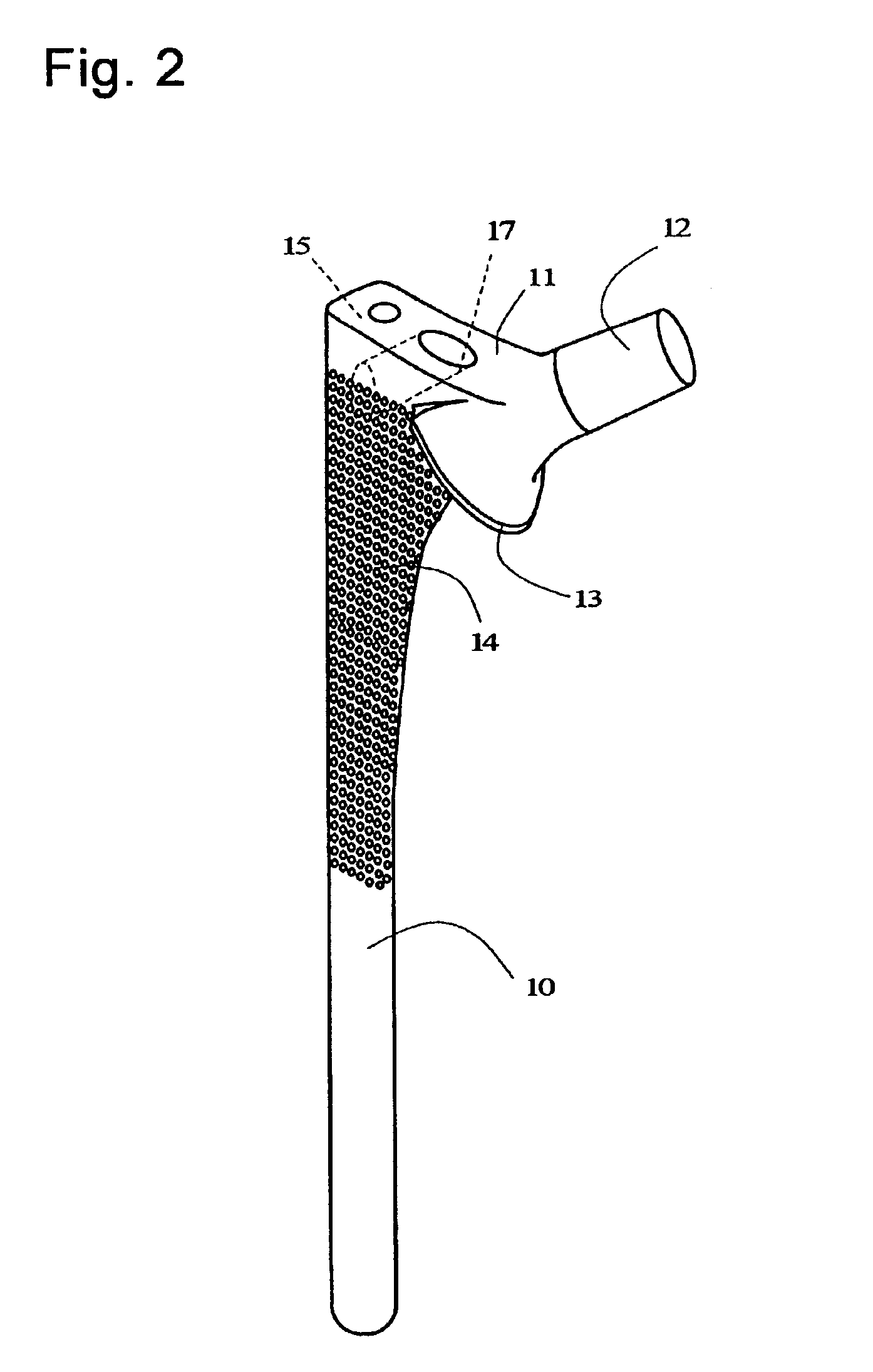
[0023]The stem 10 has an upper end portion 11 to face a proximal side of a human body and a backside 15 to face a greater trochanter 33. The upper end portion 11 has a rod 12 projecting obliquely upward. A ball 21 is engaged with, and fixed to, the rod 12. The ball 21 is slidably engaged with the socket 22, to form a joint that performs a relative motion. The stem 10 has a number of fine projections 14 formed on a surface of its portion that is to be positioned between a greater trochanter 30 and a small trochanter 33. The fine projections 14 are formed, for example, by plasma-spray-applie...


PUM


Abstract

A stem of an artificial hip joint is capable of removing a gap that may be formed between a proximal portion of a femur and a backside of the stem. The stem has an upper end portion to face a proximal side and a backside to face a greater trochanter and is adapted for insertion into, and fixation to, a medullary space of a femur. The stem has a through bore opened both to the upper end portion and the vicinity of proximal end of the backside.

Description

FIELD OF THE INVENTION[0001]The present invention relates to a stem of an artificial hip joint.PRIOR ART[0002]FIG. 5 shows one example of conventional artificial hip joint. The artificial hip joint has a stem 10 and a head 20. The stem 10 is fixed to a femur 30, and the head 20 is constituted of a ball 21 and a socket 22 to be fixed to a cotyle 41 of a pelvis 40. The stem 10 has an upper end portion 11 facing a proximal side of a human body, a rod 12 projecting obliquely upward is formed on the upper end portion 11, and the ball 21 is engaged with, and fixed to, the rod 12. The ball 21 is slidably engaged with the socket 22 to form a joint that performs a relative motion. The stem 10 has a flange 13 formed on an upper end of its side where the stem 10 faces a small trochanter 34 of the femur 30. Before the stem 10 is fixed, a proximal end (upper end) of the femur 30 is excised, to form an opening portion 32 in a medullary space 31.[0003]Conventionally, the stem 10 of an artificial h...

Claims


Application Information

Patent Timeline
Patent Type & Authority Patents(United States)
IPC IPC(8): A61F2/30A61F2/36A61F2/46A61B17/16A61F2/00A61F2/32A61F2/34A61F2/26
CPCA61B17/8802A61B17/8841A61F2/30767A61F2/367A61B17/1659A61B17/1668A61F2/32A61F2/34A61F2/36A61F2/3676A61F2002/30322A61F2002/30606A61F2002/30795A61F2002/30891A61F2002/30892A61F2002/30894A61F2002/3208A61F2002/3611A61F2002/3625A61F2002/3631A61F2002/365A61F2002/3664A61F2002/3684A61F2002/4631A61F2250/0026A61F2002/30878A61F2002/368
Inventor MITSUGI, NAOTOKOSHINO, TOMIHISA
Owner KOSHINO TOMIHISA
Why Eureka
Try Eureka